Driver controller for EMU traction system

A driver controller and traction system technology, which is applied to railway braking systems, operating mechanisms of railway vehicle brakes, locomotives, etc. The effect of reliability

Active Publication Date: 2019-03-15
XIAN KAITIAN RAILWAY ELECTRICAL
View PDF5 Cites 0 Cited by
  • Summary
  • Abstract
  • Description
  • Claims
  • Application Information

AI Technical Summary

Problems solved by technology

[0003] The purpose of the present invention is to provide a driver controller for the EMU traction system, which solves the problem that the existing driver controller endangers the safe operation of the EMU due to the breakage of the fixing screw

Method used


Image

  • Driver controller for EMU traction system
  • Driver controller for EMU traction system
  • Driver controller for EMU traction system

Examples


Embodiment Construction

[0017] The present invention will be described in detail below in conjunction with the accompanying drawings and specific embodiments.

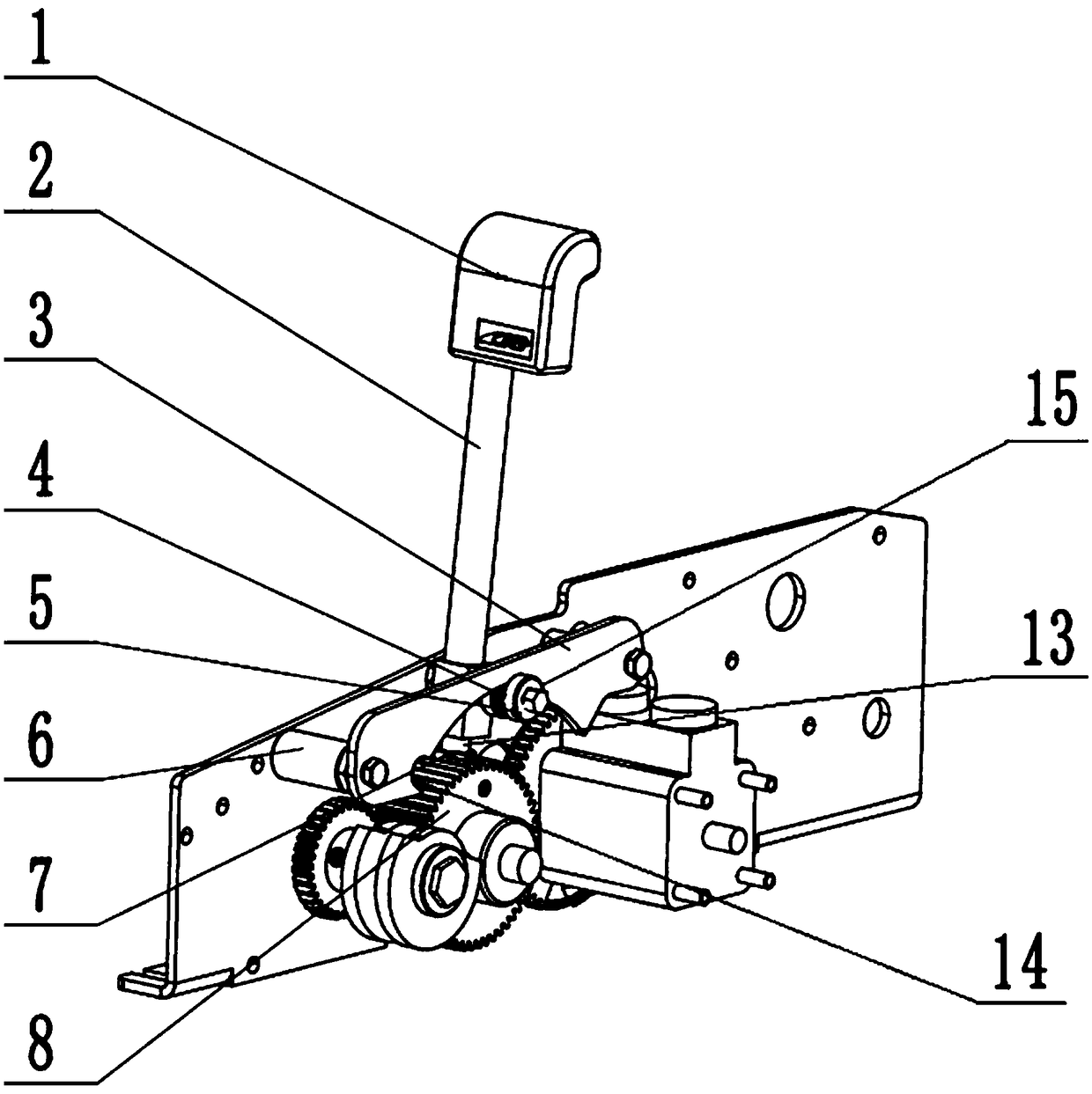
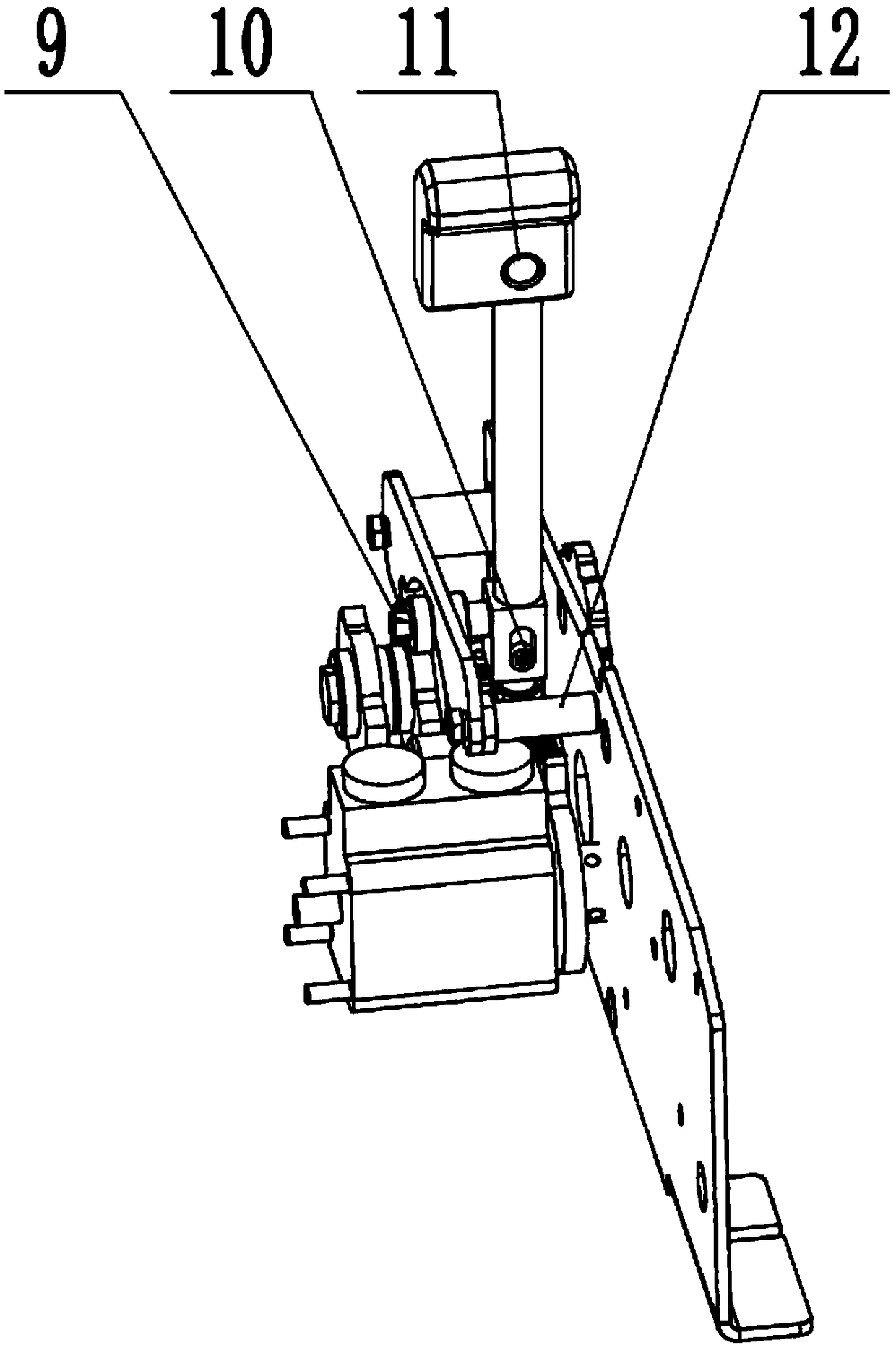
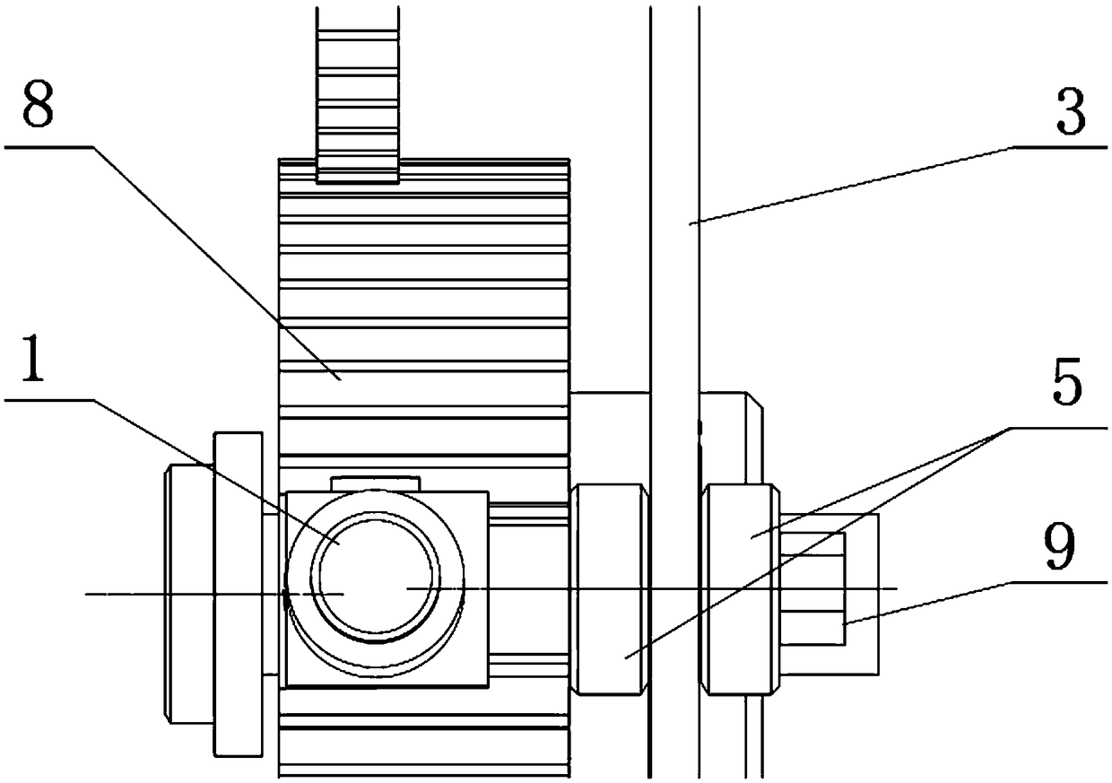
[0018] The structure of the driver controller for the traction system of an EMU provided by the present invention is as follows: Figure 1-Figure 3 As shown, it includes the driving gear 8 and the limiting plate 3 located on the same side of the left side plate, the limiting rod 13 is fixed on the driving gear 8, and the handle is also included. The lower end of the handle is fixed with a connector and is provided with an internal hollow cavity , the upper part of the limiting rod 13 is sleeved in the cavity and the two are connected by a spring, the connecting head is provided with a limiting groove along the length of the handle, and the upper part of the limiting rod 13 is located in the region of the limiting groove to fix the limiting screw 10 , the connecting head is fixed with a roller shaft 9 along the direction perpendicular to the h...


PUM


Abstract

The invention discloses a driver controller for the traction system of an EMU, which includes a driving gear, a limiting plate, and a handle. A limiting rod is fixed on the driving gear. The upper part of the stop rod is sleeved in the cavity and the two are connected by a spring. The connector is provided with a limit slot along the length of the handle. The limit screw is fixed in the area of ​​the limit slot on the limit rod. The connector is along the vertical direction. A roller shaft is fixed in the direction of the handle, a rolling bearing is sheathed on the roller shaft, and a side roller is respectively sheathed on the rolling bearing at the positions on both sides of the limiting plate. In the traction system of an EMU according to the present invention, the driver controller adds side rollers on both sides of the rolling bearing to slide with the limit plate in an orbital manner, and uses the cooperation between the two sides of the side rollers and the two sides of the limit plate to eliminate the original torsion The shear stress ensures the operational reliability of the LC handle assembly, thereby improving the reliability of the driver's controller.

Description

technical field [0001] The invention belongs to the technical field of locomotive equipment, and in particular relates to a driver controller for the traction system of an EMU. Background technique [0002] The driver controller is mainly used in the traction controller of the EMU. The driver of the locomotive completes the control functions such as the traction and braking functions of the EMU through the cooperation of the handle and the limit plate. However, the existing driver controller is used During the process, the fixing screw often breaks. For example, the CRH5 driver controller in my country is mainly used in the traction controller of the CRH5 standard EMU. Because the handle assembly of this kind of driver controller is along the limit plate When the outer contour rotates, the limit plate will produce resistance to the rolling bearing installed on the roller shaft in the handle assembly to make the handle assembly rotate, and the rotation will generate torsional s...

Claims


Application Information

Patent Timeline
Patent Type & Authority Patents(China)
IPC IPC(8): B61H13/02B61C17/00
CPCB61C17/00B61H13/02
Inventor 赵波金鑫刘俊明焦蕾
Owner XIAN KAITIAN RAILWAY ELECTRICAL
Why Eureka
Try Eureka