Bearing clearance detector

A technology of bearing clearance and detector, applied in the direction of mechanical clearance measurement, etc., can solve problems such as unreasonable structural design, affecting detection efficiency, complex bearing tooling structure, etc.

Active Publication Date: 2017-06-30
C&U CO LTD +1
View PDF7 Cites 7 Cited by
  • Summary
  • Abstract
  • Description
  • Claims
  • Application Information

AI Technical Summary

Problems solved by technology

[0003] The structure design of the bearing fastening tool used to fasten the bearing on the existing bearing tester is unreasonable. Usually the bearing is placed vertically and fixed. For example, in the "Bearing Angular Play Tester" with patent number 201410664513.2, the mandrel is inserted into the bearing On the ring, there are also bearings that are placed horizontally, such as the "Bearing Axial Clearance Measurement Tooling" with patent number 201410817587.5; however, the bearing tooling with the above structure has complex structures and inconvenient fastening and disassembly of the bearings, which affects the detection efficiency.

Method used


Image

  • Bearing clearance detector
  • Bearing clearance detector
  • Bearing clearance detector

Examples


Embodiment Construction

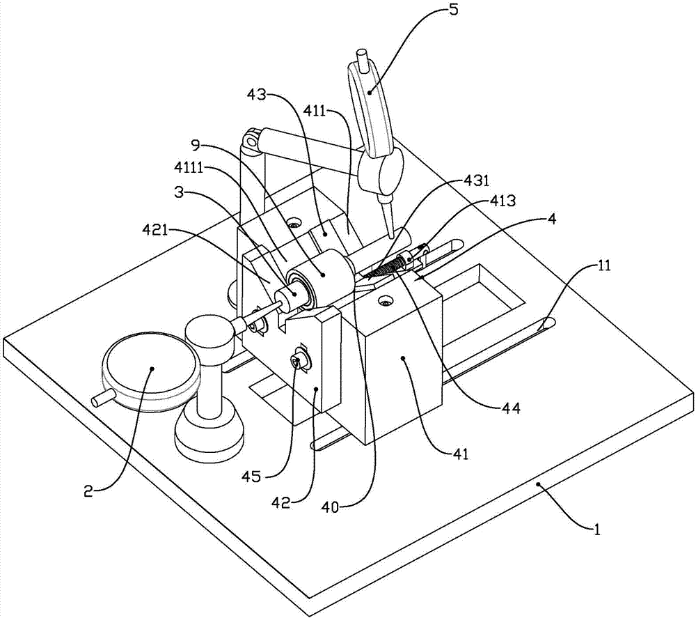
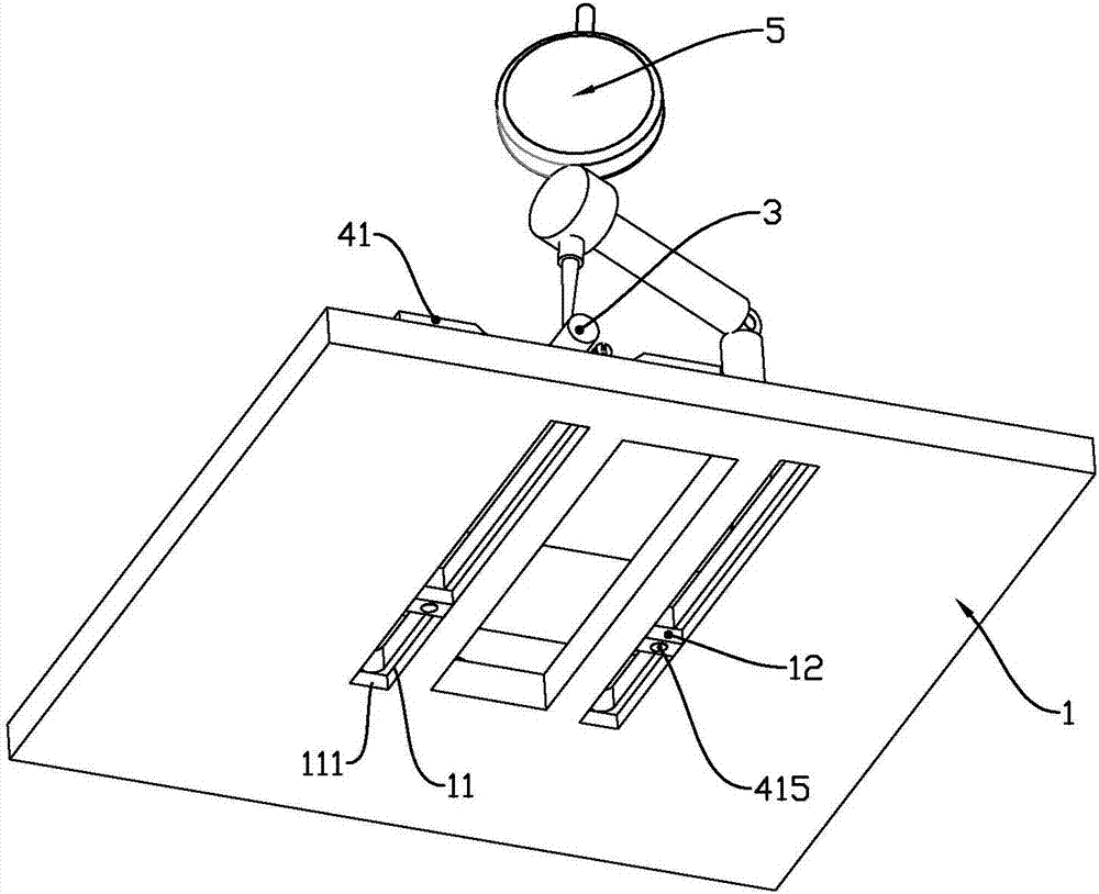
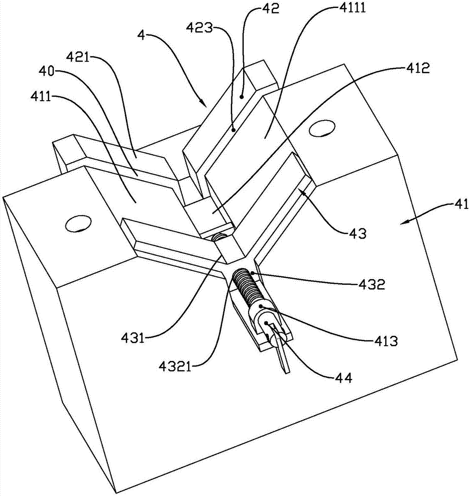
[0019] See attached figure 1 To attach Figure 4 , a bearing clearance detector disclosed in the present invention comprises a substrate 1, an axial clearance detection gauge 2, a mandrel 3 inserted on the inner ring of a bearing 9 to be tested, and a bearing fixing tool 4, and the axial clearance detection The table head of Table 2 is in conflict with the axial end of the mandrel 3. The bearing fixing tool 4 includes a support seat 41 fixed on the base plate 1. The support seat 41 is provided with a clamping mechanism for fastening the outer ring of the bearing to be tested. The top of the support seat 41 is provided with a V-shaped groove 411, and the clamping mechanism includes a first clamping block 42 and a second clamping block 43 arranged at intervals along the length direction of the V-shaped groove 411. The first clamping block 42 and the second clamping block 43 are spaced apart to form a clamping cavity 40 for axially clamping the outer ring of the bearing 9 to be ...


PUM


Abstract

The invention relates to a bearing clearance detector comprising a substrate, an axial clearance detection meter, a mandrel and a bearing fixing tool, wherein a meter head of the axial clearance detection meter is in an abutting fit relation with an axial end of the mandrel, the bearing fixing tool comprises a support seat fixed on the substrate, a clamping mechanism used for firmly fixing an outer ring of a bearing to be detected is arranged on the support seat, a top part of the support seat is provided with a V-shaped groove, the clamping mechanism comprises a first clamping block and a second clamping block that are arranged along a length direction of the V-shaped groove at an interval, a clamping cavity used for axially clamping the outer ring of the bearing to be detected is formed in the interval between the first clamping block and the second clamping block, the V-shaped groove is at least partially positioned in the clamping cavity and forms a V-shaped positioning groove body, and each of top parts of the first clamping block and the second clamping block is provided with a V-shaped opening; an angle clearance detection meter is correspondingly matched on the other end of the mandrel of which one end is matched with the axial clearance detection meter, and a meter head of the angle clearance detection meter is in the abutting fit relation with a circumferential surface of the mandrel. The bearing clearance detector is reasonable in structure design, and the bearing to be detected is convenient to install, clamp and dismount.

Description

technical field [0001] The invention relates to a bearing clearance detection device. Background technique [0002] Bearing clearance is also called bearing clearance. The so-called bearing clearance refers to the amount of movement when the bearing is not installed on the shaft or bearing box, the inner ring or the outer ring is fixed, and then the unfixed side of the bearing clearance is moved radially or axially . [0003] The structure design of the bearing fastening tool used for fastening the bearing on the existing bearing tester is unreasonable. Usually, the bearing is placed and fixed vertically. For example, in the "Bearing Angular Play Tester" with patent number 201410664513.2, the mandrel is inserted into the bearing On the ring, there are also bearings that are placed horizontally, such as the "Bearing Axial Clearance Measurement Tooling" with patent number 201410817587.5; however, the bearing tooling with the above structure has complex structures, and the be...

Claims


Application Information

Patent Timeline
IPC IPC(8): G01B5/14
CPCG01B5/14
Inventor 李难民郭长建
Owner C&U CO LTD
Why Eureka
Try Eureka