
Stand column and cover beam splicing structure

A column and cover beam technology, applied to bridges, bridge parts, bridge construction, etc., can solve the problems of large impact on the surrounding environment, long construction period, high site requirements, etc., to ensure safe operation, good component quality, and reduce construction site Effect

Inactive Publication Date: 2017-06-30
SHANGHAI MUNICIPAL ENG DESIGN INST GRP +1
View PDF5 Cites 6 Cited by
  • Summary
  • Abstract
  • Description
  • Claims
  • Application Information

AI Technical Summary

Problems solved by technology

[0003] The disadvantages are that the construction period is long, there are many on-site procedures, the requirements for the site are high, the support system has high requirements for the foundation, the safety is poor, the pollution is serious, and it has a great impact on the surrounding environment

Method used


Image

  • Stand column and cover beam splicing structure
  • Stand column and cover beam splicing structure
  • Stand column and cover beam splicing structure

Examples


Embodiment Construction

[0026] In order to make the above objects, features and advantages of the present invention more comprehensible, specific implementations of the present invention will be described in detail below in conjunction with the accompanying drawings. It should be noted that all the drawings of the present invention are in simplified form and use inaccurate scales, and are only used to facilitate and clearly assist the purpose of illustrating the embodiments of the present invention.

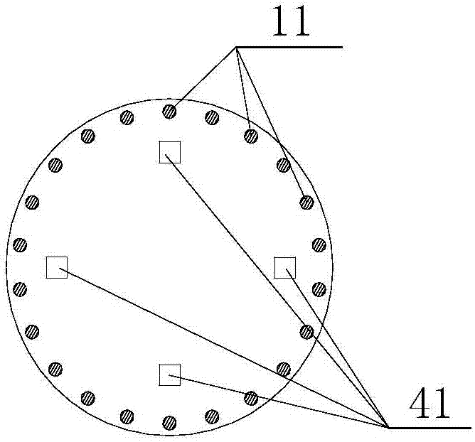
[0027] The column and cover beam assembly structure provided by the present invention, such as Figure 1 to Figure 5c As shown, it is used for the splicing of the column 10 and the cover beam 20. The bottom of the column 10 is fixed on the platform 30, and a number of steel bars 11 protrude from the top of the column 10; a number of metal corrugations are embedded in the cover beam 20 Pipe 21, the bottom of the metal bellows 21 is flush with the bottom surface of the cover beam 20; the position of the m...


PUM


Abstract

The invention relates to a stand column and cover beam splicing structure used for splicing of a stand column and a cover beam. The bottom of the stand column is fixed to a bearing platform. A plurality of steel bars extend out of the top of the stand column. A plurality of metal corrugated pipes are embedded in the cover beam. The bottoms of the metal corrugated pipes are flush with the bottom face of the cover beam. The metal corrugated pipes correspond to the steel bars in position. A splicing joint between the stand column and the cover beam is filled with high-strength mortar or epoxy splicing glue. Grouting channels arranged in the cover beam. The two ends of each metal corrugated pipe communicate with a mortar inlet and a mortar outlet through the grouting channels correspondingly. According to the stand column and cover beam splicing structure, a traditional bridge building mode is changed, no bracket or formwork exists on a construction site, the site construction period is greatly shortened, the labor intensity of workers is relieved, and requirements for the construction site are reduced; the procedures of bracket foundation processing and bracket formwork erection on the site are omitted, and the economical efficiency is good; and meanwhile, adverse impact on the surroundings is reduced.

Description

technical field [0001] The invention relates to the field of bridge structure construction, in particular to an assembled structure of a column and a cover beam. Background technique [0002] At present, the connection between the bridge cover beam and the column is usually cast in-situ by the bracket method, that is, the bracket and the formwork are erected, and the column reinforcement is bound on the cap platform. After the concrete pouring and curing of the column is completed, the cover beam reinforcement is bound, and then the cover beam concrete is poured , Generally, a construction period is at least 2 to 3 weeks. [0003] The disadvantages are that the construction period is long, there are many on-site procedures, the requirements for the site are high, the support system has high requirements for the foundation, the safety is poor, the pollution is serious, and it has a great impact on the surrounding environment. Contents of the invention [0004] The inventio...

Claims


Application Information

Patent Timeline
Patent Type & Authority Applications(China)
IPC IPC(8): E01D21/00E01D19/00
CPCE01D21/00E01D19/00
Inventor 沈维芳冀振龙崔晨卢永成刘经熠朱世峰
Owner SHANGHAI MUNICIPAL ENG DESIGN INST GRP
Learn More