
Apparatus and method for testing conductivity of battery diaphragm

A battery diaphragm and conductivity technology, which is applied in the direction of measuring devices, measuring resistance/reactance/impedance, measuring electrical variables, etc., can solve problems such as complex operation, low test efficiency, and long test time

Active Publication Date: 2017-06-27
SHENZHEN ZHONGXING NEW MATERIAL TECH CO LTD
View PDF6 Cites 6 Cited by
  • Summary
  • Abstract
  • Description
  • Claims
  • Application Information

AI Technical Summary

Problems solved by technology

[0004]The above method is more complicated to operate, and it is necessary to test the resistance value of at least four layers of diaphragms separately, and the resistance value of one layer, two layers, three layers and four layers can be compared It is easy to fit a linear curve and calculate the surface resistance of the diaphragm; the number of tests is large, the operation process is complicated, the test takes a long time, and the test efficiency is low; and four or more tests require a large amount of diaphragm samples. It is also the average value of the surface resistance of multiple sample diaphragms

Method used


Image

  • Apparatus and method for testing conductivity of battery diaphragm
  • Apparatus and method for testing conductivity of battery diaphragm
  • Apparatus and method for testing conductivity of battery diaphragm

Examples


Embodiment

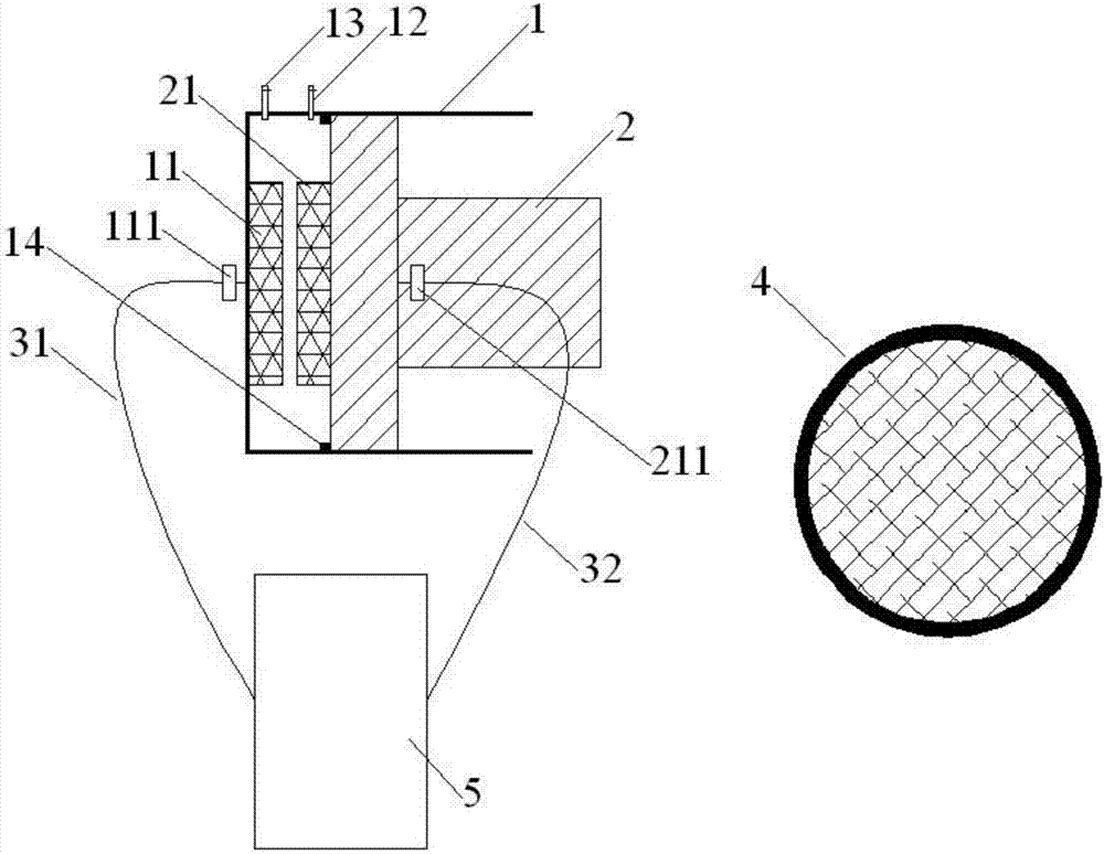
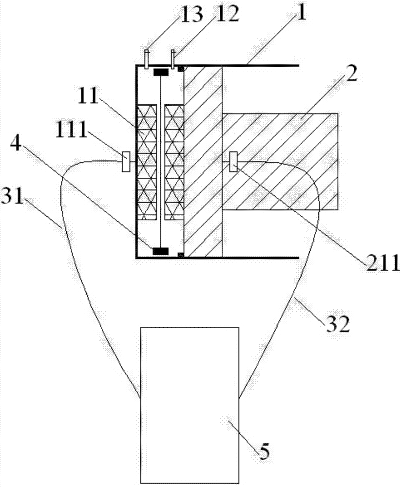
[0046] The battery diaphragm conductivity testing device of this example, such as figure 1 As shown, it includes a conductivity cell housing 1 , a conductivity cell cover 2 , a diaphragm clamp 4 and a conductivity meter 5 .

[0047] The conductance cell housing 1 is a cylindrical barrel-shaped structure with one end open. Inside the conductance cell housing 1, there is a first circular conductance electrode sheet 11 at the bottom end, and the outer surface of the bottom of the conductance cell housing 1 has a first electrode external interface 111. , the first electrode external interface 111 is connected to the first circular conductance electrode piece 11 by wire; the conductance cell cover 2 is disassembled and fixed on the open end of the conductance cell housing 1, and the conductance cell cover 2 is inserted into the conductance cell housing 1 to connect with it A relatively closed cavity is formed, the inner surface of the conductance cell cover 2 has a second circular ...


PUM

PropertyMeasurementUnit
Thicknessaaaaaaaaaa
Thicknessaaaaaaaaaa
Thicknessaaaaaaaaaa

Abstract

The application discloses an apparatus and method for testing the conductivity of a battery diaphragm. The apparatus comprises a conductance cell housing, a conductance cell cover, a diaphragm clamp, and a conductivity meter. The conductance cell housing is in a cylindrical shape with one open end, comprises a first circular conductance electrode piece at the inner surface of the bottom, and a first electrode external interface electrically connected with the first circular conductance electrode piece and on the outer surface. The two electrode external interfaces are used to be connected with the conductivity meter. The conductance cell cover is detachably inserted and fixed to the open end of the conductance cell housing, comprises a second circular conductance electrode piece at the inner surface, and a second electrode external interface electrically connected with the second circular conductance electrode piece and on the outer surface. A vacuum valve port and a liquid injection valve port are arranged on the sidewall of the housing. The diaphragm clamp is an interlocked annular structure, has an outer diameter matching the inner diameter of the conductance cell housing, is in parallel with the two conductance electrode pieces and coaxial with the two conductance electrode pieces. The apparatus is simple in structure and easy to operate and can accurately and accurately measure the conductivity and the resistance of the diaphragm.

Description

technical field [0001] The present application relates to the field of testing equipment for lithium-ion battery diaphragms, in particular to a device and method for testing the conductivity of battery diaphragms. Background technique [0002] In recent years, the development of new energy has attracted attention, especially the rapid development of lithium-ion batteries, which has become the focus of attention in the new energy industry. Lithium-ion batteries are composed of four key materials: positive electrode, negative electrode, diaphragm and electrolyte. The diaphragm is located between the positive and negative electrodes, which plays an isolation role, prevents direct contact between the positive and negative electrodes and short circuit, and allows ion conduction and prevents electronic conduction. Microporous structure: The microporous structure of the diaphragm restricts the ion conduction rate of lithium ions, which directly affects the performance of lithium io...

Claims


Application Information

Patent Timeline
IPC IPC(8): G01R27/02
CPCG01R27/02Y02E60/10
Inventor 郑鹏吴晓丹张辉樊孝红王哲
Owner SHENZHEN ZHONGXING NEW MATERIAL TECH CO LTD
Learn More