Multiple Disc Clutch

A clutch and multi-disc technology, applied in the direction of clutches, friction clutches, mechanical drive clutches, etc., can solve the problems of high cost and expensive manufacturing of multi-disc clutches, and achieve the effect of precise structure and saving axial installation space

Active Publication Date: 2020-03-17
SCHAEFFLER TECH AG & CO KG
View PDF10 Cites 0 Cited by
  • Summary
  • Abstract
  • Description
  • Claims
  • Application Information

AI Technical Summary

Problems solved by technology

[0003] If the multi-disk clutch is provided for high torques, the outer carrier is usually manufactured as a drawn part and the teeth for torque-locking engagement of the friction discs are applied by means of rolling, which is cost-intensive and causes multiple Disc clutches get expensive to manufacture

Method used


Image

  • Multiple Disc Clutch
  • Multiple Disc Clutch
  • Multiple Disc Clutch

Examples


Embodiment Construction

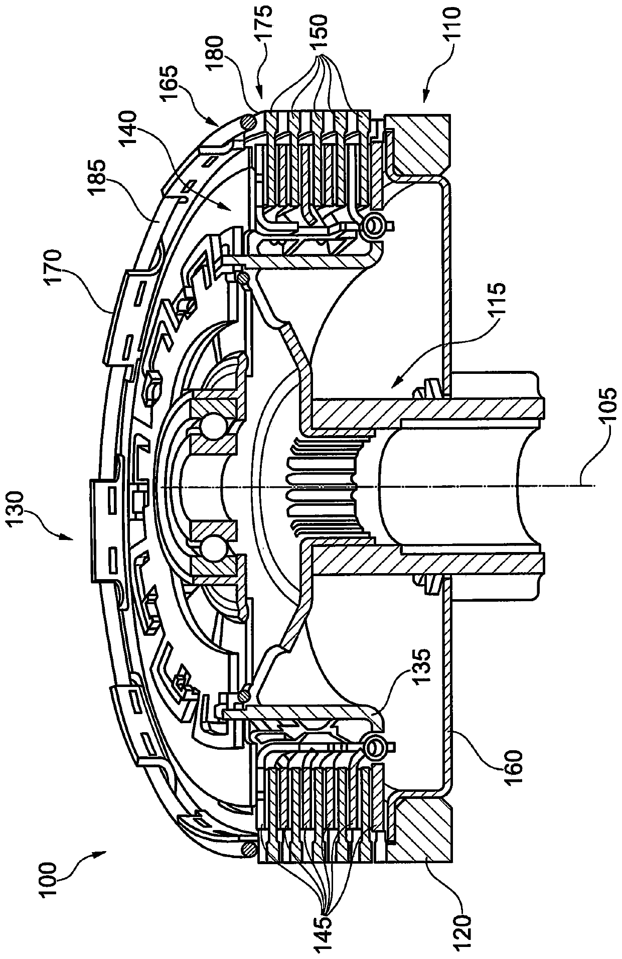
[0023] figure 1 A multi-plate clutch 100 for use in motorcycles, in particular scooters, is shown. The motorcycle can have a piston reciprocating internal combustion engine with one or more cylinders, and any cylinder of the internal combustion engine can be approximately 170-250 cm 3 , for example about 200cm 3 .

[0024] The multi-disc clutch 100 includes an axis of rotation 105 about which an input side 110 and an output side 115 are rotatably arranged. In the embodiment shown, the output side 115 is located radially on the inside and the input side 110 is located radially on the outside, but the reverse arrangement is also possible. In the embodiment shown, a ring gear 120 is mounted on the input side 110 , in which ring generally a primary gear meshes, said primary gear being fastened directly on the crankshaft driving the engine.

[0025] The multi-disk clutch 100 includes an outer carrier 130 , which is connected here to the input side 110 , and an inner carrier 135...


PUM


Abstract

A multi-plate clutch comprises an outer carrier rotatable about an axis of rotation; plurality of friction elements each having a radial extension, the outer carrier having recesses corresponding to the extensions through which the extensions extend to establish torque-locking connections; and a support ring which rests on the radial outer side of the outer support. In this case, the support ring lies axially between a first and an adjacent second friction element located at an axial end.

Description

technical field [0001] The invention relates to a multi-disc clutch. In particular, the invention relates to a multi-disc clutch for motorcycles. Background technique [0002] A multi-disc clutch for a motorcycle includes an inner carrier and an outer carrier, the carriers being rotatably arranged about a common axis of rotation. A plurality of clutch plates are torque-locked and axially movably fitted into the inner carrier, and a plurality of friction plates are torque-locked and axially movably fitted into the outer carrier. These clutch disks and friction disks are assembled alternately in the axial direction to form disk stacks. In order to transmit torque between the inner carrier and the outer carrier, the disc stack is pressed together in the axial direction. [0003] If the multi-disk clutch is provided for high torques, the outer carrier is usually manufactured as a drawn part and the teeth for torque-locking engagement of the friction discs are applied by means...

Claims


Application Information

Patent Timeline
Patent Type & Authority Patents(China)
IPC IPC(8): F16D13/52F16D13/60F16D13/58
CPCF16D13/52F16D13/58F16D13/60F16D13/683
Inventor S·霍伊贝格尔C·拉贝尔
Owner SCHAEFFLER TECH AG & CO KG
Why Eureka
Try Eureka