
Electromagnetic buffering unit of casting device

An electromagnetic and buffer plate technology, applied in the direction of the line, etc., can solve the problems of low energy utilization, general effect, increased recoil stroke or multi-stage recoil mechanism series connection, etc., to achieve the effect of improving buffer efficiency and simple structure

Active Publication Date: 2017-06-27
DALIAN MARITIME UNIVERSITY
View PDF6 Cites 2 Cited by
  • Summary
  • Abstract
  • Description
  • Claims
  • Application Information

AI Technical Summary

Problems solved by technology

This method has a low utilization rate of gas internal energy, and the effect is average.
Ultra-long or tandem ultra-long recoil technology, increasing the recoil stroke or connecting multi-stage recoil mechanisms in series, greatly reducing the recoil force, and the multi-stage recoil mechanism is complex

Method used


Image

  • Electromagnetic buffering unit of casting device
  • Electromagnetic buffering unit of casting device
  • Electromagnetic buffering unit of casting device

Examples


Embodiment Construction

[0026] In order to make the purpose, technical solutions and advantages of the embodiments of the present invention clearer, the technical solutions in the embodiments of the present invention will be clearly and completely described below in conjunction with the drawings in the embodiments of the present invention. Obviously, the described embodiments It is a part of embodiments of the present invention, but not all embodiments. Based on the embodiments of the present invention, all other embodiments obtained by persons of ordinary skill in the art without creative efforts fall within the protection scope of the present invention.

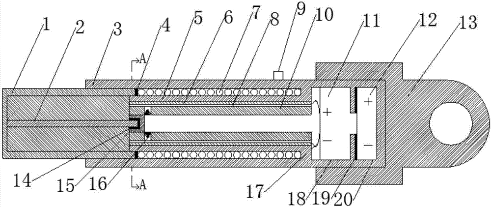
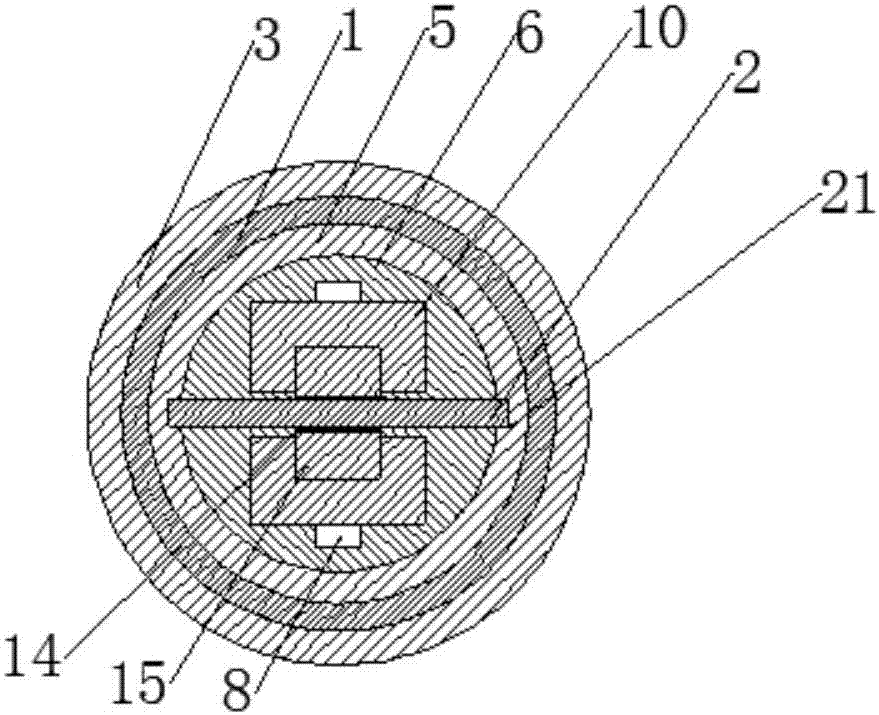
[0027] figure 1 It is a structural schematic diagram of the electromagnetic buffer device of a thrower of the present invention, as figure 1 As shown, the device of this embodiment includes:

[0028] Buffer plate, conductor buffer guide rail, buffer module, detection module, guide rail shell, insulation structure, control module and battery for ...


PUM


Abstract

The invention provides an electromagnetic buffering unit of a casting device. The electromagnetic buffering unit comprises a buffering plate, conductor buffering guide rails, a buffering module, a detection module, guide rail outer shells, an insulation structure, a control module and a storage battery precharging the control module. One end of the buffering plate is connected to the rear end of the casting device, and the other end of the buffering plate is arranged in the buffering guide rails and provided with the buffering module. The two sides of the buffering plate are embedded into grooves of the guide rail outer shells and move relative to the buffering guide rails. The insulation structure is located between the conductor buffering guide rails and the guide rail shells. The detection module is used for sending a trigger signal to the control module when detecting that the buffering plate is at a movement state. The control module is used for receiving the triggering signal sent by the control module and controlling a closed loop composed of the buffering module and the conductor buffering guide rails. The buffering module is used for generating ampere force opposite to the movement direction of the buffering plate in the closed loop. By adoption of the electromagnetic buffering unit, buffering efficiency of the recoil force of the casting device is improved.

Description

technical field [0001] Embodiments of the present invention relate to the technical field of buffer devices, in particular to an electromagnetic buffer device for a thrower. Background technique [0002] The thrower is a kind of equipment that is powered by compressed air or gunpowder and throws ropes and lifebuoys to the target. According to its power source, it can be divided into pneumatic thrower and gunpowder thrower. [0003] No matter which of the above-mentioned power sources will produce a large recoil after throwing, the current throwing recoil buffer includes: forward rush technology, that is, first accelerate the thrower to half of the recoil, and then decelerate to the device to be launched after throwing. This method is relatively complex in technology and poor in control performance. The muzzle brake technology controls the high-pressure gas flow distribution and airflow velocity to generate a braking force on the thrower and reduce the kinetic energy of the...

Claims


Application Information

Patent Timeline
Patent Type & Authority Applications(China)
IPC IPC(8): B63C9/26
CPCB63C9/26
Inventor 张彬张兴东牛小兵吴宛青江欣李伟
Owner DALIAN MARITIME UNIVERSITY
Learn More