Welding spot indicating device

A technology for indicating devices and solder joints, applied in auxiliary devices, welding equipment, auxiliary welding equipment, etc., can solve problems such as high cost of adding a single unit, decreased accuracy of welding positions, and easy wear and tear

Inactive Publication Date: 2017-06-27
BEIJING BORGWARD AUTOMOBILE CO LTD
View PDF10 Cites 1 Cited by
  • Summary
  • Abstract
  • Description
  • Claims
  • Application Information

AI Technical Summary

Problems solved by technology

This technical solution has the following disadvantages: 1. The mechanical solder point guide occupies the operating space of the welding torch, which will hinder the welding operation; 2. The cost of adding a mechanical solder point guide is high, and it is easy to wear, resulting in a decrease in the accuracy of the welding position

Method used


Image

  • Welding spot indicating device
  • Welding spot indicating device
  • Welding spot indicating device

Examples


Embodiment Construction

[0024] In the drawings, the same or similar reference numerals are used to denote the same or similar elements or elements having the same or similar functions. Embodiments of the present invention will be described in detail below in conjunction with the accompanying drawings.

[0025] In the description of the present invention, the terms "central", "longitudinal", "transverse", "front", "rear", "left", "right", "vertical", "horizontal", "top", " The orientation or positional relationship indicated by "bottom", "inner", "outer", etc. is based on the orientation or positional relationship shown in the drawings, and is only for the convenience of describing the present invention and simplifying the description, rather than indicating or implying the referred device or element Must have a specific orientation, be constructed and operate in a specific orientation, and therefore should not be construed as limiting the scope of the invention.

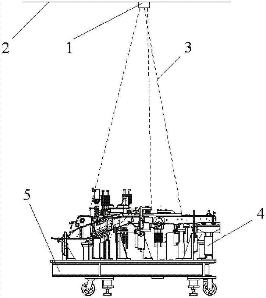
[0026] figure 1 It is a schematic ...


PUM


Abstract

The invention discloses a welding spot indicating device. The welding spot indicating device comprises a light beam emitter, and the light beam emitter emits light beams (3) and illuminates and indicates the welding spot positions on workpieces. The welding spot indicating device indicates the welding positions through the light beams so that the operation space of a welding gun for welding cannot be occupied, and the phenomenon that the accuracy of the welding positions is lowered due to abrasion is avoided.

Description

technical field [0001] The invention relates to the field of welding technology, in particular to a welding point indicating device. Background technique [0002] In the process of manual spot welding, there are often some solder joints with poor visibility, and the reference position features on the visible side are not obvious, resulting in large deviations in the position of the welding solder joints, resulting in quality risks; there are also more solder joints in some stations, There will be miswelding and missing welding. This is especially true at manual stations where automotive body welding is performed. [0003] In the prior art, mechanical solder joint guidance is used to solve the above problems. This technical solution has the following disadvantages: 1. The mechanical solder point guide occupies the operating space of the welding torch, which will hinder the welding operation; 2. The cost of adding a mechanical solder point guide is high, and it is easy to we...

Claims


Application Information

Patent Timeline
IPC IPC(8): B23K37/00
CPCB23K37/00
Inventor 王文标
Owner BEIJING BORGWARD AUTOMOBILE CO LTD
Why Eureka
Try Eureka