Intra-region intelligent micro-grid node layout method
A layout method and micro-grid technology, applied in the field of power systems, to simplify the complexity, facilitate implementation, and avoid damage
- Summary
- Abstract
- Description
- Claims
- Application Information
AI Technical Summary
Problems solved by technology
Method used
Image
Examples
specific Embodiment 1
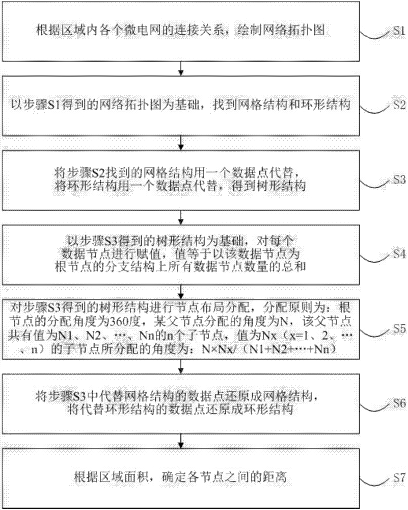
[0030] The flow chart of the node layout method of the smart microgrid in the region in this embodiment is as follows figure 1 shown. The smart microgrid node layout method in this area includes the following steps:
[0031] S1. Draw a network topology diagram according to the connection relationship of each microgrid in the region;
[0032] S2. Based on the network topology diagram obtained in step S1, find a grid structure and a ring structure;
[0033] S3. The grid structure found in step S2 is replaced by a data point, and the ring structure is replaced by a data point to obtain a tree structure;
[0034] S4. Based on the tree structure obtained in step S3, assign a value to each data node, and the value is equal to the sum of the numbers of all data nodes on the branch structure with the data node as the root node;
[0035] S5. Perform node layout allocation on the tree structure obtained in step S3. The allocation principle is: the allocation angle of the root node is...
specific Embodiment 2
[0039] The node layout method of the smart microgrid in the region of this embodiment is further limited on the basis of the specific embodiment 1: the leaves of the tree structure are peeled off sequentially, if:
[0040] There is only one data node left, which serves as the root node;
[0041] There are two remaining data nodes, and any one of the data nodes serves as the root node.
[0042] Let's take a set of data as an example to further describe the above two embodiments in detail:
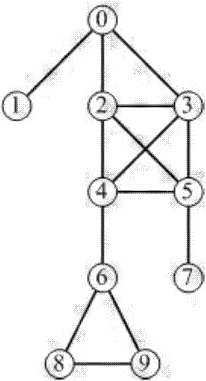
[0043] S1. According to the connection relationship of each microgrid in the region, draw a network topology map, such as figure 2 shown.
[0044] S2. Based on the network topology diagram obtained in step S1, a grid structure and a ring structure are found; wherein, 0 nodes, 2 nodes, 3 nodes, 4 nodes and 5 nodes form a grid structure, and 6 nodes, 8 nodes and 9 nodes The nodes form a ring structure.
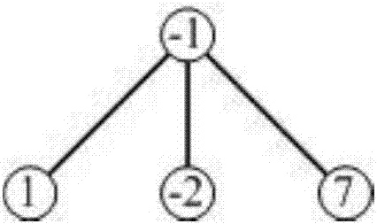
[0045] S3. The grid structure found in step S2 is replaced by a data point, and the r...
PUM
 Abstract
Description
Claims
Application Information
 - R&D
- Intellectual Property
- Life Sciences
- Materials
- Tech Scout
- Unparalleled Data Quality
- Higher Quality Content
- 60% Fewer Hallucinations
Browse by: Latest US Patents, China's latest patents, Technical Efficacy Thesaurus, Application Domain, Technology Topic, Popular Technical Reports.
© 2025 PatSnap. All rights reserved.Legal|Privacy policy|Modern Slavery Act Transparency Statement|Sitemap|About US| Contact US: help@patsnap.com


