a head-mounted display

A display and display technology, applied in instruments, optics, electrical components, etc., can solve the problems of poor viewing effect, misalignment between the optical center and the display center, and increased weight, so as to achieve comfortable and convenient use, simplified product structure, and compact size. Effect

Active Publication Date: 2020-01-17
SHENZHEN NED OPTICS CO LTD
View PDF11 Cites 0 Cited by
  • Summary
  • Abstract
  • Description
  • Claims
  • Application Information

AI Technical Summary

Problems solved by technology

[0007] Both the above-mentioned second and third schemes can realize the adjustment of the diopter (diopter) and the interpupillary distance at the same time, but it is necessary to drive the bilateral lenses or lens barrels to move at the same time to realize the adjustment of the interpupillary distance, which is not only complicated in structure and large in size, but also Since there is only one display screen, when the interpupillary distance is adjusted, the effective display image of the display screen and the double-sided lenses or lens barrels will move relative to each other, resulting in a misalignment between the optical center and the display center, which directly affects the display effect of the edge screen; at the same time, the diopter During the adjustment process, moving the lens or lens barrel will change the distance between the lens or lens barrel and the display screen at the same time, as well as the distance between the human eye and the lens or lens barrel, that is, changing the eye-to-eye distance, and the change of the eye-to-eye distance It will reduce the accuracy of diopter adjustment, resulting in poor viewing effect
[0008] In addition, since head-mounted displays are currently developing in the direction of compact size, light weight, ease of wearing, and lightening loads, complex structures will inevitably lead to increased volume and weight of head-mounted displays, which will affect the use of head-mounted displays.

Method used


Image

  • a head-mounted display
  • a head-mounted display
  • a head-mounted display

Examples


Embodiment Construction

[0052] In order to make the purpose, technical solutions and advantages of the embodiments of the present invention clearer, a clear and complete description will be made below in conjunction with the technical solutions in the embodiments of the present invention. Obviously, the described embodiments are part of the embodiments of the present invention, and Not all examples. Based on the embodiments of the present invention, all other embodiments obtained by persons of ordinary skill in the art without making creative efforts belong to the protection scope of the present invention.

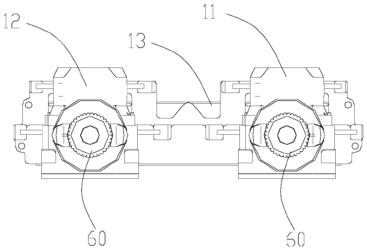
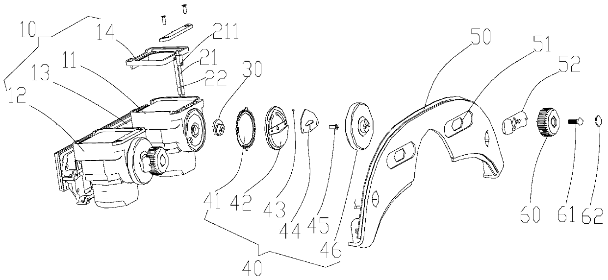
[0053] The structure of the head-mounted display in the preferred embodiment of the present invention is as follows: figure 1 and figure 2 As shown, the main frame 10 is included, and the left and right display screens are arranged on the main frame 10, and the left and right eyepieces corresponding to the left and right display screens are arranged on the main frame 10; The distance between t...


PUM


Abstract

The invention relates to a head-mounted display, comprising a main body frame, left and right display screens and left and right eyepieces corresponding to the left and right display screens are arranged on the main body frame; The distance between the display screen and the eyepiece, and the diopter and interpupillary distance adjustment mechanism used to adjust the distance between the two eyepieces; Rotation and sliding operations are used to adjust the diopter and interpupillary distance of the head-mounted display, respectively. That is, the diopter of the head-mounted display can be adjusted by rotating the knob assembly, and the interpupillary distance of the head-mounted display can be adjusted by sliding the knob assembly, which is not only easier to operate, but also simplifies the product structure, making the head-mounted display. The product is more compact, lighter, and more comfortable and convenient to use.

Description

technical field [0001] The present invention relates to the technical field of intelligent terminals, and more specifically, to a head-mounted display. Background technique [0002] With the continuous development of electronic devices towards ultra-miniaturization, as well as the development of new computer, microelectronics, optoelectronic devices and communication theories and technologies, wearable computing, a new model based on "people-oriented" and "integration of man and machine" has become possible. . Applications are emerging in military, industrial, medical, education, consumer and other fields. In a typical wearable computing system architecture, the head-mounted display device is a key component. The head-mounted display device guides the video image light emitted by the micro-image display (such as transmissive or reflective liquid crystal display, organic electroluminescent device, DMD device) to the user's pupil through optical technology, and the user's ne...

Claims


Application Information

Patent Timeline
Patent Type & Authority Patents(China)
IPC IPC(8): G02B27/01H04N13/344
CPCG02B27/0176G02B2027/0178H04N13/344H04N2213/001G02B2027/0159G02B27/0179G02B2027/0181G02B2027/0154H04N13/332G02B6/0016G02B27/0172
Inventor 刘冬华曹鸿鹏彭华军薛冰涛
Owner SHENZHEN NED OPTICS CO LTD
Why Eureka
Try Eureka