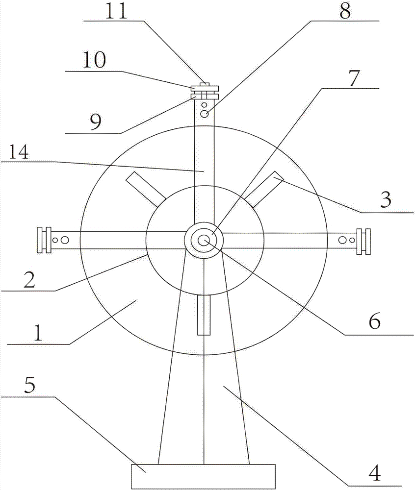
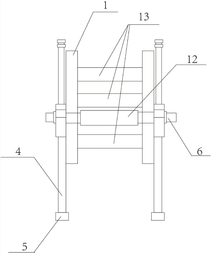
Rotating wheel structure of tail water generator set

A technology of generating sets and runners, which is applied in ocean energy power generation, engine components, machines/engines, etc. It can solve the problems of unsuitable construction of large, medium and small hydropower stations, low civil construction cost of tail water generating sets, and unsuitability for ordinary households. , to achieve the effect of improving energy conversion rate, saving materials, and high utilization rate of water energy

Pending Publication Date: 2017-06-20
天津市创维机械设备制造有限公司
View PDF5 Cites 0 Cited by
  • Summary
  • Abstract
  • Description
  • Claims
  • Application Information

AI Technical Summary

Problems solved by technology

[0002] At present, there are many remote mountainous areas in our country, each family lives relatively far away, the power grid wires cannot be erected, and the local water volume is small, so it is not suitable for the construction of large, medium and small hydropower stations. The existing hydropower generation is mainly large hydropower stations and small and medium hydropower stations. , and limited by the size of the water flow, it needs water storage to generate electricity, which is not suitable for ordinary households. People often use tail water to generate electricity. The civil construction cost of tail water generating units is low and the efficiency is high. The main disadvantage of the generator set is that the design of the runner or water wheel is relatively complicated, and the repair cost after damage is high. The runner structure of the tail water generator set is the most important and expensive component of the tail water generator set. A single component accounts for about the entire 30% of the cost of the tail water generator set, the strength of the runner is not high, and the runner is easily damaged during use. The tail water generator set relies on the runner to absorb energy, and the runner directly determines the important performance indicators of the tail water generator set

Method used


Image

  • Rotating wheel structure of tail water generator set
  • Rotating wheel structure of tail water generator set

Examples


Embodiment Construction

[0022] The technical solutions of the present invention will be clearly and completely described below in conjunction with the accompanying drawings. Apparently, the described embodiments are some of the embodiments of the present invention, but not all of them. Based on the embodiments of the present invention, all other embodiments obtained by persons of ordinary skill in the art without making creative efforts belong to the protection scope of the present invention.

[0023] In the description of the present invention, it should be noted that the terms "center", "upper", "lower", "left", "right", "vertical", "horizontal", "inner", "outer" etc. The indicated orientation or positional relationship is based on the orientation or positional relationship shown in the drawings, and is only for the convenience of describing the present invention and simplifying the description, rather than indicating or implying that the referred device or element must have a specific orientation, ...


PUM


Abstract

The invention aims to provide a rotating wheel structure of a tail water generator set. The structure comprises rotating wheels, reinforcing rings, slide devices, a bracket, a first bolt, a bearing base, channel steel, a support leg, a second bolt, a center main shaft and a connecting plate, and is characterized in that the rotating wheels are vertically distributed at two ends of the center main shaft; the circular reinforcing rings are respectively arranged on the two rotating wheels; the reinforcing rings are fixedly connected with the rotating wheels; and the slide devices are arranged on the outer side walls of the two rotating wheels, and are fixedly connected with the rotating wheels. One end of the channel steel is fixedly connected with the support leg through the second bolt, and the channel steel is tightly connected with the bracket through the connecting plate, so that the fixation of the bearing base is guaranteed under the stress condition of the rotating wheels; the reinforcing rings are arranged on the rotating wheels, and adopt materials of stainless steel, so that the strength of the rotating wheels can be reinforced, and the damage of the rotating wheels due to excessive stress in the use process is prevented; and the structure has the advantages of high wear resistance and corrosion resistance.

Description

technical field [0001] The invention relates to the technical field of tail water power generation, in particular to a runner structure of a tail water generating set. Background technique [0002] At present, there are many remote mountainous areas in our country, each family lives relatively far away, the power grid wires cannot be erected, and the local water volume is small, so it is not suitable for the construction of large, medium and small hydropower stations. The existing hydropower generation is mainly large hydropower stations and small and medium hydropower stations. , and limited by the size of the water flow, it needs water storage to generate electricity, which is not suitable for ordinary households. People often use tail water to generate electricity. The civil construction cost of tail water generating units is low and the efficiency is high. The main disadvantage of the generator set is that the design of the runner or water wheel is relatively complicated...

Claims


Application Information

Patent Timeline
Patent Type & Authority Applications(China)
IPC IPC(8): F03B17/06F03B13/00
CPCF03B13/00F03B17/065Y02E10/30
Inventor 陈剑常淳辉
Owner 天津市创维机械设备制造有限公司
Why Eureka
Try Eureka