
Current sensor abnormity detection method and device

A current sensor and anomaly detection technology, applied in measuring devices, instruments, measuring electrical variables, etc., can solve problems such as system impact, inability to determine current sensors, and inability to determine whether current sensor detection is abnormal or damaged, etc., to improve safety and reliability. sex, loss avoidance effect

Inactive Publication Date: 2017-06-16
SINENG ELECTRIC CO LTD
View PDF5 Cites 2 Cited by
  • Summary
  • Abstract
  • Description
  • Claims
  • Application Information

AI Technical Summary

Problems solved by technology

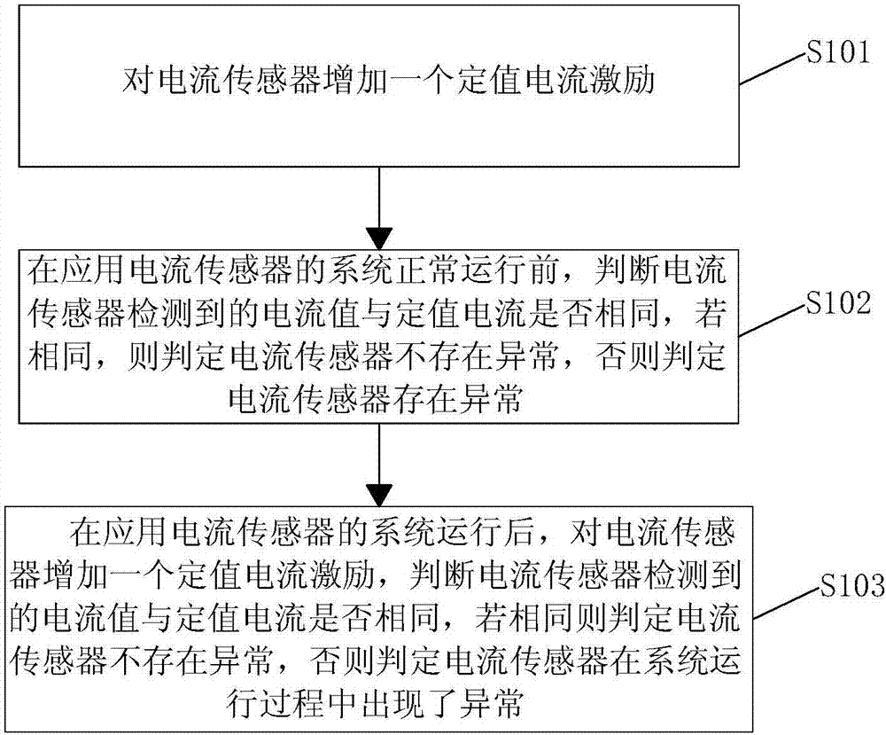
In the traditional application of current sensors, the system using the current sensor is only to connect a current sensor in series on the circuit to be detected, which is used to detect the current of the device in real time, but this application has certain disadvantages: before the system is running, the current cannot be determined The sensor checks whether there is abnormality or damage. At this time, the operating system, because the load condition is unknown, does not know the current on the wire, so it can only be detected by the current sensor. However, because the working condition of the current sensor is unknown, it is impossible to determine whether the current sensor detects is the actual current
Even if the current sensor is abnormal, it cannot be known in time, so if it continues to be used, it will affect the entire system. In serious cases, there may be a situation where there should be current but it is not detected. At this time, if it is mistaken that there is no current passing through , the operation of the system is prone to danger

Method used


Image

  • Current sensor abnormity detection method and device
  • Current sensor abnormity detection method and device

Examples


Embodiment Construction

[0016] In order to facilitate understanding of the present invention, the present invention will be described more fully hereinafter with reference to the related drawings. Preferred embodiments of the invention are shown in the accompanying drawings. However, the present invention may be embodied in many different forms and is not limited to the embodiments described herein. Rather, these embodiments are provided so that a thorough and complete understanding of the present disclosure is provided. It should be noted that when an element is referred to as being "connected" to another element, it can be directly connected to the other element or intervening elements may also be present. Unless otherwise defined, all technical and scientific terms used herein have the same meaning as commonly understood by one of ordinary skill in the art to which this invention belongs. The terms used herein in the description of the present invention are for the purpose of describing specific...


PUM


Abstract

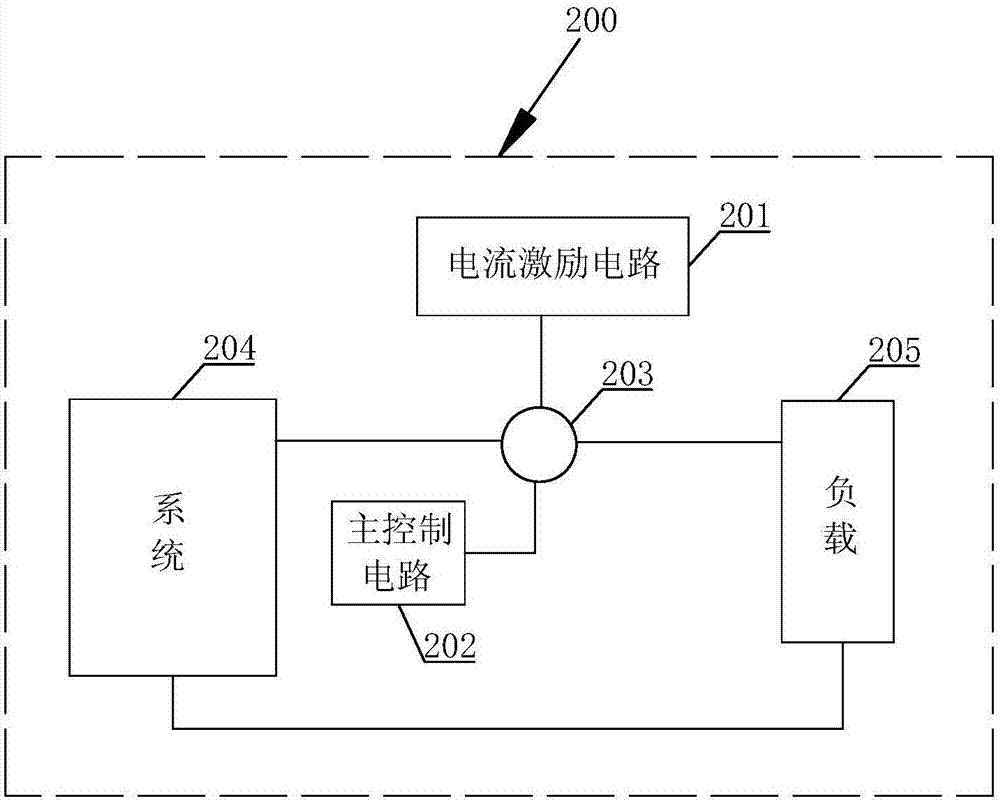
The invention discloses a current sensor abnormity detection method and device. The device comprises a current excitation circuit and a master control circuit. The current excitation circuit is connected with a current sensor to be detected and used for arranging fixed value current excitation for the current sensor to be detected. The master control circuit is connected with the current sensor to be detected and used for judging whether the current value detected by the current sensor is the same with the fixed value current. If the judgment result is yes, the current sensor has no abnormality, or the current sensor has abnormality. One fixed value current excitation is additionally arranged through the current excitation circuit, whether the current value detected by the current sensor is the same with the fixed value current is judged through the master control circuit, and the current sensor has no abnormality if the judgment result is yes, or the current sensor has abnormality so that abnormity of the current sensor can be simply and rapidly judged, the safety and the reliability of the system can be enhanced and unnecessary loss can be avoided.

Description

technical field [0001] The present invention relates to the technical field of current sensor detection, and in particular, to a method and device for abnormality detection of a current sensor. Background technique [0002] A current sensor is a detection device that can sense the information of the measured current, and can transform the sensed information into electrical signals that meet certain standards or other required forms of information output according to certain rules, so as to meet the needs of information requirements for transmission, processing, storage, display, recording and control. In the traditional application of the current sensor, the system applying the current sensor only connects a current sensor in series on the circuit to be detected to detect the current of the device in real time, but this application has certain disadvantages: the current cannot be determined before the system is running. The sensor detects whether there is any abnormality or...

Claims


Application Information

Patent Timeline
IPC IPC(8): G01R35/00
CPCG01R35/00
Inventor 付贺张林江
Owner SINENG ELECTRIC CO LTD
Learn More