
Executor of elastic element for volume balance

An actuator and elastic technology, applied in the direction of belts/chains/gears, mechanical equipment, transmission devices, etc., can solve problems such as insecurity, and achieve the effect of simple manufacturing

Active Publication Date: 2017-06-13
ROBERT BOSCH GMBH
View PDF8 Cites 0 Cited by
  • Summary
  • Abstract
  • Description
  • Claims
  • Application Information

AI Technical Summary

Problems solved by technology

However, the variable volume of the inner chamber has the result that it is not ensured that the screwing action interacts with the incompressible fluid in every position of the bracket and in every mounting position of the actuator. achieve contact

Method used


Image

  • Executor of elastic element for volume balance
  • Executor of elastic element for volume balance
  • Executor of elastic element for volume balance

Examples


Embodiment Construction

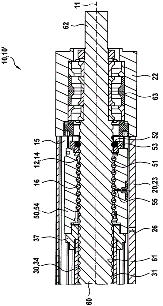
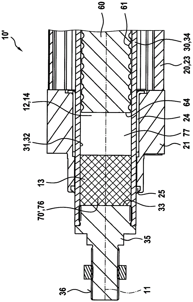
[0027] figure 1 A longitudinal section through the drive-side end of the actuator 10 according to the first embodiment of the invention is shown. The actuator 10 has a housing 20 consisting of a main body 23, a first end block (in figure 2 and 3 The middle is No. 21) and the second end block 22 is formed. The main body 23 is preferably extruded from aluminum so that it has a constant, tubular cross-sectional shape along the longitudinal axis 11 . A rotary bearing 63 is accommodated in the second end piece 22 , with which the threaded spindle 60 is mounted rotatably about the longitudinal axis 11 . The rotary bearing 63 is preferably designed in the form of a radial rolling bearing, wherein in the present case it comprises a plurality of oblique ball bearings which are pressed against one another without play. A threaded spindle 60 extends through the second end piece 22 , wherein the threaded spindle protrudes outwardly from the housing 20 with a drive journal 62 . Via t...


PUM


Abstract

The invention relates to an executor (10) having a shell (20) and a bracket (30). The bracket can be linearly supported on the shell (20) in a direction of a longitudinal axis (11); the bracket (30) outwardly extends out of the shell (20) along a longitudinal axis; the shell and the bracket co-define an internal room (12); the volume of the internal room is changed when the bracket (30) moves relative to the shell (20); a thread main shaft (60) can be rotationally supported on the shell (20) by a rotary bearing corresponding to the longitudinal axis (11); the thread main shaft extends into a hollow room (31) of the bracket (30); the bracket (30) is provided with a nut; the nut is arranged in the internal room (12) and in a rotary screwing action with the thread main shaft (60); elastic elements (70,70`) are distributed into the hollow room (31) of the bracket (30); and the elements are elastically deformed when the bracket (30) moves corresponding to the shell (20).

Description

technical field [0001] The invention relates to an actuator according to the invention. Background technique [0002] An actuator is known from DE 10 2007 043 391 A1. The actuator has a housing and a bracket, wherein the bracket is mounted on the housing so as to be linearly movable in the direction of the longitudinal axis, wherein the bracket extends from the housing in the direction of the longitudinal axis to stick out. The housing and the bracket collectively define an interior chamber whose volume is changed upon movement of the bracket relative to the housing. In addition, a threaded spindle is provided, which is mounted rotatably on the housing with respect to the longitudinal axis by means of a rotary bearing, wherein the threaded spindle protrudes into the hollow space of the carrier. In addition, the carrier is provided with a nut, which is arranged in the inner chamber and which is in screwing action with the threaded spindle. [0003] On the one hand, the me...

Claims


Application Information

Patent Timeline
Patent Type & Authority Applications(China)
IPC IPC(8): F16H25/20
CPCF16H25/20F16H25/2021
Inventor K.默瓦斯托M.肖尔茨
Owner ROBERT BOSCH GMBH
Learn More