
General purpose engine

A general-purpose engine and engine technology, applied to engine components, engine cooling, machine/engine, etc., can solve the problems of large number of components, increased cost, and reduced operability of blowing

Active Publication Date: 2017-06-13
KAWASAKI MOTORS LTD
View PDF4 Cites 0 Cited by
  • Summary
  • Abstract
  • Description
  • Claims
  • Application Information

AI Technical Summary

Problems solved by technology

[0004] In this way, in the existing engine structure, the cover member covering the blowing opening is separated from the filter cover, so the installation and removal of the cover member must be carried out as a different operation from the installation and removal of the filter cover. Therefore, the operability of blowing is reduced, and the cost is increased due to the large number of parts

Method used


Image

  • General purpose engine
  • General purpose engine
  • General purpose engine

Examples


Embodiment Construction

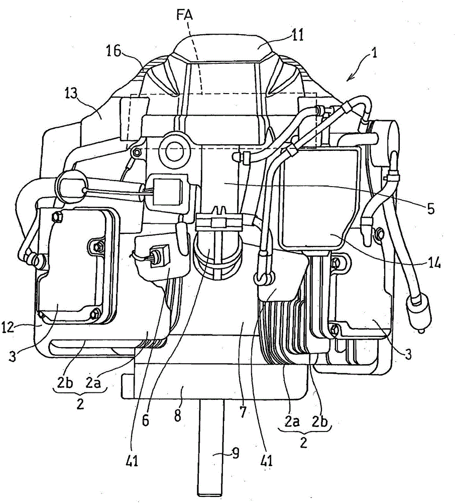
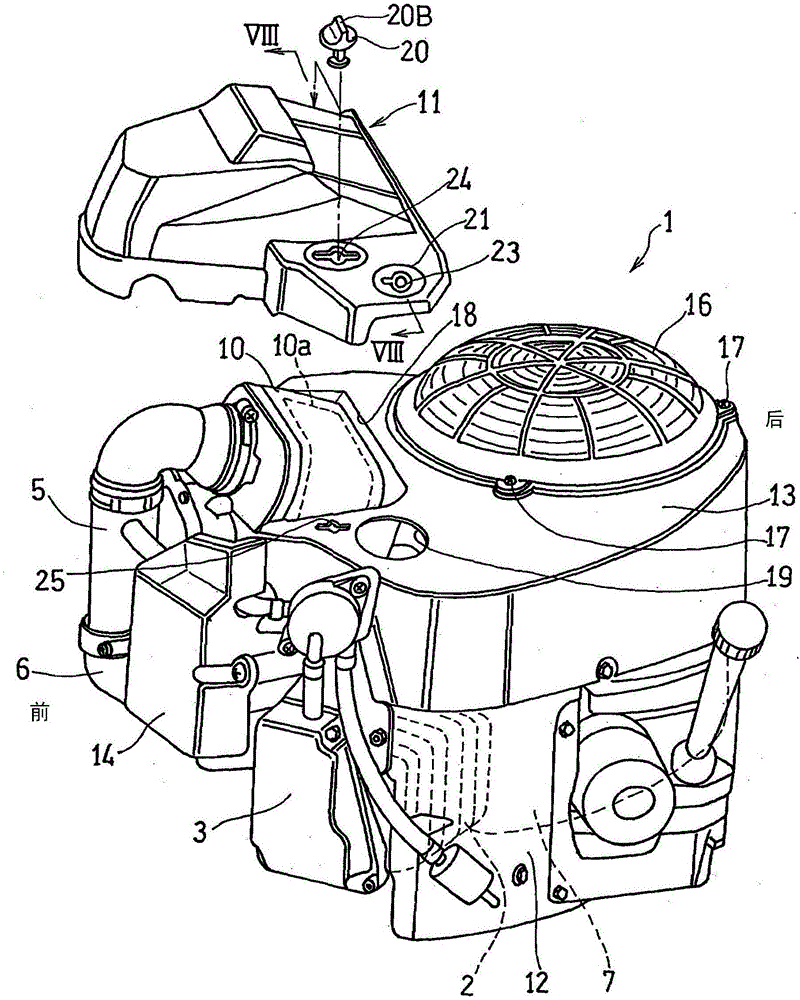
[0038] Hereinafter, one embodiment of the present invention will be described with reference to the drawings. figure 1 It is a front view showing a schematic configuration of a general-purpose engine according to an embodiment of the present invention. figure 1 The illustrated general-purpose engine 1 is a small air-cooled two-cycle engine, and is used as a drive source for a working machine such as a lawnmower.

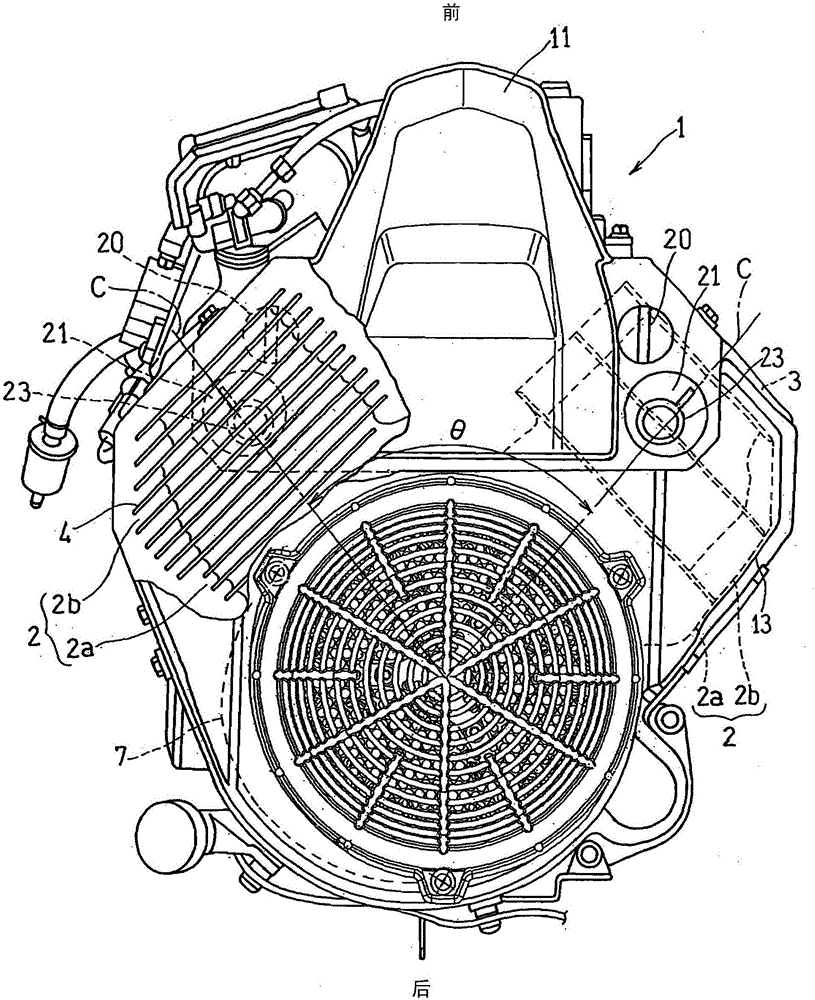
[0039] If according to image 3 As can be clearly seen, the engine 1 is a V-shaped two-cylinder engine in which a pair of cylinder units 2 , left and right, including a cylinder 2 a and a cylinder head 2 b are arranged in a V shape. The angle θ formed by the cylinder axes C and C of the cylinder units 2 and 2 is 70 to 90°, and is 80° in this example. The tops of these cylinder units 2, 2 are respectively made of figure 1 The cylinder head cover 3,3 covers. A plurality of cooling fins 4 are formed on the outer periphery of each cylinder unit 2 .

[0040] Between ...


PUM


Abstract

The invention provides an air cooling general purpose engine with cleaning windows, which is reduced in part number and is improved in blowing operability. The general purpose engine with the cleaning windows is an air cooling general purpose engine having air cylinder units (2) including air cylinders (2a) and air cylinder covers (2b). The general purpose engine includes a housing (13) at least covering the air cylinder units (2); a filter cover (11) which is detachably arranged on the housing (13), and a filter portion (10a) covering an air filter (10); blowing windows (19) which are formed on the housing (13) and opposite to gaps (40) between a plurality of fins (4, 4); and sealing portions (21) which are formed on the filter cover (11) and are used for blocking the blowing windows (19).

Description

technical field [0001] The present invention relates to a general-purpose engine with a window for cleaning used as a drive source of a working machine such as a lawnmower. Background technique [0002] For example, a small air-cooled general-purpose engine is generally used as a drive source of a working machine such as a lawnmower. When such a working machine is continuously used for a certain period of time, the cut grass may accumulate as garbage in the gaps between the cylinder head and the cooling fins around the cylinder, which are components of the engine, and cause clogging, thereby impairing the cooling function of the engine. . [0003] Therefore, the work of removing the dust accumulated in the gaps of the cooling fins is performed periodically or at any time. On the other hand, the filter unit holding the filter element of the air cleaner is also prone to clogging, and therefore requires maintenance such as cleaning or replacement on a regular basis or at any ...

Claims


Application Information

Patent Timeline
Patent Type & Authority Applications(China)
IPC IPC(8): F02B77/00F02M35/04A01D69/00
CPCA01D69/002F02B77/00F02M35/04F01P1/02F01P11/12F02B77/04F02F1/065F02M35/0201F02M35/024F02F1/34
Inventor J·D·库克A·U·西库斯
Owner KAWASAKI MOTORS LTD
Learn More