
An optimization method for the eccentricity of the rotor mass center of the engine core machine

An optimization method and machine rotor technology, applied in the direction of engine components, machines/engines, liquid fuel engines, etc., can solve problems such as low assembly efficiency, increased engine manufacturing costs, and repeated assembly, so as to reduce assembly manufacturing costs and improve assembly success rate effect

Active Publication Date: 2020-01-17
AECC SHENYANG ENGINE RES INST
View PDF2 Cites 0 Cited by
  • Summary
  • Abstract
  • Description
  • Claims
  • Application Information

AI Technical Summary

Problems solved by technology

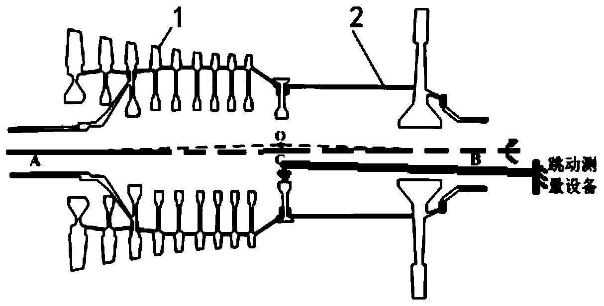
[0005] Although the above core machine rotor assembly process is feasible, the controllability of the key process parameter OC value is poor, and it is easy to cause repeated assembly due to OC retesting out of tolerance during the transfer process, and the high pressure caused by the excessive center of mass eccentricity of the core machine rotor Vibration also occurs from time to time, resulting in low assembly efficiency, indirectly increasing the manufacturing cost of the engine, and there are problems such as the process does not dig out the inherent vibration performance of the existing structure of the machine parts.

Method used


Image

  • An optimization method for the eccentricity of the rotor mass center of the engine core machine
  • An optimization method for the eccentricity of the rotor mass center of the engine core machine
  • An optimization method for the eccentricity of the rotor mass center of the engine core machine

Examples


Embodiment Construction

[0048]In order to make the objectives, technical solutions and advantages of the present invention clearer, the technical solutions in the embodiments of the present invention will be described in more detail below in conjunction with the drawings in the embodiments of the present invention. In the drawings, the same or similar reference numerals denote the same or similar elements or elements having the same or similar functions throughout. The described embodiments are some, but not all, embodiments of the invention. The embodiments described below by referring to the figures are exemplary and are intended to explain the present invention and should not be construed as limiting the present invention. Based on the embodiments of the present invention, all other embodiments obtained by persons of ordinary skill in the art without creative efforts fall within the protection scope of the present invention. Embodiments of the present invention will be described in detail below i...


PUM


Abstract

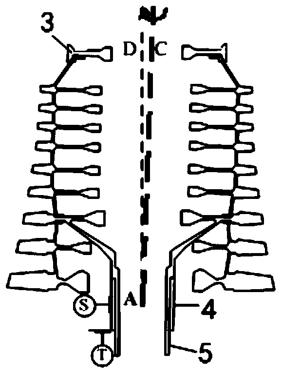
The invention discloses a method for optimizing centroid eccentricity of an engine core engine rotor. The method for optimizing centroid eccentricity of the engine core engine rotor comprises a first step of taking a minimum value of a core engine rotor joint face centroid eccentricity OC as an optimization target of the method for optimizing centroid eccentricity of the engine core engine rotor; a second step of establishing a core engine rotor centroid eccentricity prediction optimization mathematic model; a third step of obtaining a theta value corresponding when the actual spin axis OC of the labyrinth disc fitting centroid O deviated from the core engine rotor, and performing high pressure turbine rotor and high pressure compressor rotor angle rotation assembly according to the theta value. According to the method for optimizing centroid eccentricity of the engine core engine rotor, before rotor assembly, by optimal calculation, the angular phasing corresponding when the OC value is minimum is selected to guide core engine rotor assembly, and the goal of reducing centroid eccentricity of the core engine rotor and an unbalanced amount of the core engine rotor and improving high voltage rotor vibration is achieved.

Description

technical field [0001] The invention relates to the technical field of aeroengines, in particular to an optimization method for the eccentricity of the rotor mass center of an engine core machine. Background technique [0002] The rotor unbalance of the aero-engine core machine is an important factor determining the vibration response of the engine rotor, and the root cause of the unbalance is that the centroid of each discrete rotor deviates from the actual axis of rotation. A core machine rotor is assembled from a balanced high-pressure compressor rotor (HPC) and a high-pressure turbine rotor (HPT) with self-locking bolts / nuts. According to calculations, when the center of mass eccentricity of the rotor of the core machine is 0.01mm and the rotational speed is 12000r / min, it can generate a centrifugal force of about 400kg, which will break the balance state of the rotor and cause the high-pressure rotor to vibrate. [0003] refer to figure 1 , theoretically, the centroid...

Claims


Application Information

Patent Timeline
Patent Type & Authority Patents(China)
IPC IPC(8): F01D5/10F04D29/66
CPCF01D5/10F04D29/666F04D29/668
Inventor 刘清军吴法勇刘振东金彬赵洪丰史新宇张伟
Owner AECC SHENYANG ENGINE RES INST
Learn More