Support-type traveling device and overall rotating method thereof

A walking device and bracket-type technology, which is applied in the field of bracket-type walking devices, can solve the problems of low ground pressure, drastic changes in frame posture, and high stability, and achieve the effects of low ground pressure, flexible walking, and high stability

Active Publication Date: 2017-06-13
苏州弘盈工程装备科技有限公司
View PDF15 Cites 5 Cited by
  • Summary
  • Abstract
  • Description
  • Claims
  • Application Information

AI Technical Summary

Problems solved by technology

[0008] The main problems are: 1. It is necessary to pre-lay steel molds as the tracks for vehicles, which consumes extra labor and materials
2. Poor flexibility
[0011] The main problems are: 1. The wheelbase and wheelbase span of the car body are small, and the posture of the frame changes drastically on the undulating road surface, which is not conducive to the precise work of the work department, and the construction quality is affected
2. When constructing on the working surface of steel mesh or soft roadbed, the working surface will be sunken, and the vehicle will be more bumpy when walking
Reinforcement measures can be taken to avoid the depression of the working surface, but this will inevitably increase the construction cost
3. Low construction efficiency
[0014] The main problems are: 1. The bearing capacity of floating supports such as vibrating plates is limited, and they cannot support heavy work parts such as augers for a long time. When the cement viscosity is high and the road cement thickness is large, the construction quality is difficult to guarantee
2. There is still the limitation of low construction efficiency
[0017] The main problems are: 1. High cost. 2. The structure of the car body is heavy, and it is easy to damage the steel mesh or soft roadbed and other construction surfaces.
3. The working part is located on the outside of the frame, and the equipment must have a wide turning space during construction, so the flexibility is limited to a certain extent
[0020] Its main problems are: 1. When moving the track and the cross beam by means of the lifting mechanism of the working part, because the supporting span of the lifting mechanism of the working part is very small (about 2 meters), it is easy to cause the vehicle body to tilt to one side and touch the ground, or even overturned
In order to overcome this problem, the support span of the lifting mechanism of the working part can be considered to be greatly increased, but this will obviously reduce the moving stroke of the working part
2. Unable to realize the rotation of the angle of the body
Restricted by the direction of the track layout, the body can only translate along the front, rear and left and right directions, and it is difficult to complete the construction of diagonal crossing roads, curved roads and irregular areas
3. The track and the cross beam are only connected by moving pairs, which is not adaptable enough to the undulating construction surface
On rough roads, the rails on both sides cannot be guaranteed to be parallel and coplanar. When the span beam runs along the rail, if the driving force is insufficient, it is easy to slip or get stuck; if the driving force is sufficient, the span beam may pull the rail, causing the car body to Shaking, affecting the construction quality
4. When working, the support does not have the functions of leveling and height adjustment
In order to overcome this problem, a self-leveling support structure can be used for the rails on both sides, so that the rails on both sides are parallel and coplanar, but this obviously leads to an increase in system complexity and cost
[0021] Based on the above analysis, it is difficult for the frame structure scheme of the existing equipment to simultaneously obtain the advantages of large span, low ground pressure, high stability (suitable for undulating road surfaces) and flexible walking

Method used


Image

  • Support-type traveling device and overall rotating method thereof
  • Support-type traveling device and overall rotating method thereof
  • Support-type traveling device and overall rotating method thereof

Examples


Embodiment Construction

[0055] The present invention will be more fully understood from the following detailed description, which should be read in conjunction with the accompanying drawings. Detailed embodiments of the present invention are disclosed herein; however, it is to be understood that the disclosed embodiments are merely exemplary of the invention, which may be embodied in various forms. Therefore, specific functional details disclosed herein are not to be interpreted as limiting, but merely as a basis for the claims and as a teaching to one skilled in the art that, in fact, any suitably detailed embodiment may differ in any suitably detailed embodiment. The manner employs the representative basis of the present invention.

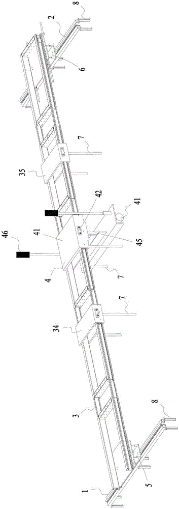
[0056] combine figure 1 As shown, the bracket type walking device includes a first rail 1, a second rail 2 and a span beam 3, the span beam 3 extends along the first direction, and the two ends of the span beam 3 are respectively supported on the first rail 1 and the ...


PUM


Abstract

The invention discloses a support-type traveling device which comprises a first rail, a second rail and a span beam. The span beam extends along a first direction, two ends of the span beam are supported on the first rail and the second rail, the span beam can move along the first rail and the second rail, a working portion is supported on the span beam and can move in the first direction relative to the span beam, the working portion comprises a flatness scraping vibration head, the flatness scraping vibration head is positioned below the span beam, the first rail can rotate in a horizontal plane and overturn in a vertical plane relative to the span beam, and the second rail can rotate in a horizontal plane and overturn in a vertical plane relative to the span beam. The invention further discloses an overall rotating method of the support-type traveling device, and rotation of the device is achieved by the aid of two steps. The support-type traveling device has the advantages that the device is wide in span, low in ground pressure, high in stability (adapting to fluctuating road surfaces) and flexible in traveling.

Description

technical field [0001] The application relates to a bracket-type walking device for construction or inspection on undulating ground, which is mainly used in technical fields such as factory floor construction, road or bridge deck concrete (cement) pavement, and agricultural flat construction. Background technique [0002] The structure of various construction machinery and construction equipment is mainly composed of two parts: the frame and the working part. Among them, the frame part needs to realize the functions of vehicle transportation, construction transition, support and guidance of the working part, etc. A good frame structure design must ensure flexible overall movement, adapt to rough ground, and support the working part stably and precisely. On this basis, the mechanical structure design should be as simple, reliable, efficient and low-cost as possible, while maximizing the simplification of auxiliary structures and personnel operations. [0003] For small and m...

Claims


Application Information

Patent Timeline
Patent Type & Authority Applications(China)
IPC IPC(8): E01C19/40
CPCE01C19/40E01C19/405
Inventor 孙建龙胡进
Owner 苏州弘盈工程装备科技有限公司
Why Eureka
Try Eureka