
A Control Method of Suction and Release Plate Based on DC Electromagnet

A DC electromagnet and board control technology, applied in the field of power electronics, can solve the problems of high cost, large size of electric control cabinet, complicated circuit, etc., and achieve the effect of cost reduction, high control precision and small volume

Active Publication Date: 2021-08-24
HUNAN KEMEIDA ELECTRIC
View PDF5 Cites 0 Cited by
  • Summary
  • Abstract
  • Description
  • Claims
  • Application Information

AI Technical Summary

Problems solved by technology

[0003] In the existing technology, the control of electromagnetic characteristics is mainly the control of magnetization and discharge. One of the existing technologies is to use a transformer step-down diode for rectification. The circuit includes a rectification transformer, a diode rectification module, and a contactor. The disadvantage of this solution is that the electric control cabinet is relatively large, the circuit is complicated, and the cost is relatively expensive.

Method used


Image

  • A Control Method of Suction and Release Plate Based on DC Electromagnet
  • A Control Method of Suction and Release Plate Based on DC Electromagnet
  • A Control Method of Suction and Release Plate Based on DC Electromagnet

Examples


Embodiment 1

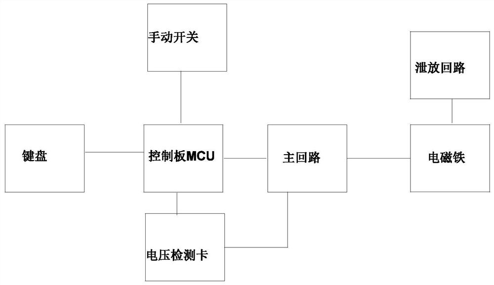
[0085] Embodiment 1: as Figure 1~5 , a method for controlling the suction and release plate based on DC electromagnets, adopting the control system of the suction and release plate, the control system of the suction and release plate includes a control device 1, a crane 2, a hook 3 and an electromagnet (4);

[0086] The hook is arranged on the driving; the electromagnet is arranged on the hook, and is used for sucking and releasing the steel plate 5;

[0087] The excitation and demagnetization of the electromagnet are controlled by the control device;

[0088] The control device includes a main circuit, a control circuit and a discharge circuit;

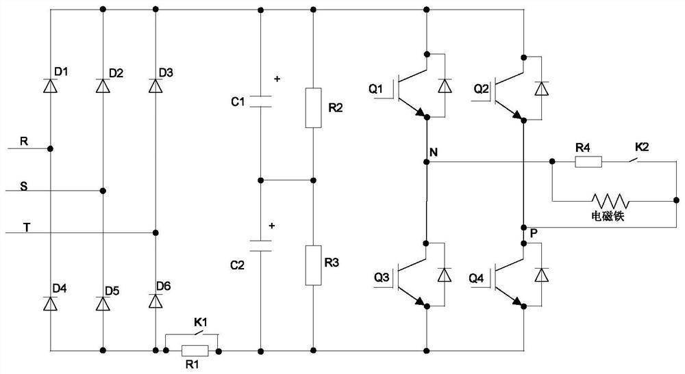
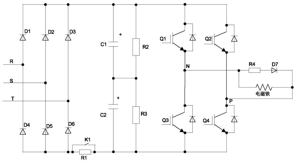
[0089] The main circuit includes a three-phase uncontrollable rectifier bridge, an energy storage capacitor branch, a voltage equalizing resistor branch and an H-bridge inverter;

[0090] The three-phase uncontrolled rectifier bridge is a rectifier bridge composed of 6 diodes;

[0091] The H-bridge inverter is a 2-bridge arm modu...


PUM


Abstract

The invention discloses a control method for suction and release plates based on DC electromagnets, including the following three controls: (A) excitation control; (B) demagnetization control; (C) energy release control; four specific control conditions are as follows: (1) One-time suction and release board control; (2) Split sheet release board control; (3) Crane travel chain control; (4) Power failure maintenance control. The control method is easy to implement, can realize the complex function of sucking and releasing plates, and has high safety and reliability.

Description

technical field [0001] The invention belongs to the technical field of power electronics and relates to a method for controlling a suction and release plate based on a DC electromagnet. Background technique [0002] An electromagnet is a device that generates electromagnetism when energized. A conductive winding matching its power is wound on the outside of the iron core. This current-carrying coil is magnetic like a magnet, and it is also called an electromagnet. Usually bar or hoof shape to make the core easier to magnetize. In addition, in order to demagnetize the electromagnet immediately when it is powered off, it is often made of soft iron or silicon steel materials that demagnetize faster. Such an electromagnet is magnetic when energized, and the magnetism disappears when the power is turned off. [0003] In the existing technology, the control of electromagnetic characteristics is mainly the control of magnetization and discharge. One of the existing technologies ...

Claims


Application Information

Patent Timeline
Patent Type & Authority Patents(China)
IPC IPC(8): B66C1/08
CPCB66C1/0218B66C1/0256B66C1/08
Inventor 丁岩赵孝正黄军荣申艳聪张海花
Owner HUNAN KEMEIDA ELECTRIC
Learn More