Roller way suitable for equipment movement

A technology of equipment and roller table, applied in the field of roller table with large stroke equipment, can solve the problems of complex control, error-prone, complex structure, etc., and achieve the effect of simple control, simple structure and large stroke.

Pending Publication Date: 2017-06-13
CISDI ENG CO LTD
View PDF12 Cites 1 Cited by
  • Summary
  • Abstract
  • Description
  • Claims
  • Application Information

AI Technical Summary

Problems solved by technology

This method requires rapid and accurate response of the roller table lifting, and needs to accurately track the position of the connecting device. The structure is complicated, the control is complicated, and it is easy to make mistakes.

Method used


Image

  • Roller way suitable for equipment movement
  • Roller way suitable for equipment movement
  • Roller way suitable for equipment movement

Examples


Embodiment

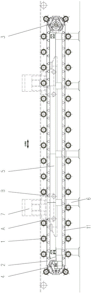
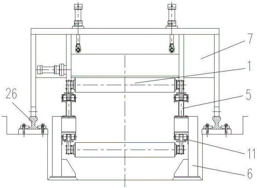
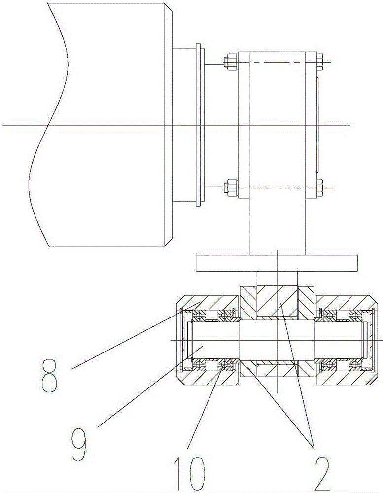
[0053] like figure 1 and figure 2 As shown, a roller table suitable for equipment movement includes a support mechanism 6, a transmission mechanism 3, a guide mechanism 5, a chain 2 and a roller 1. The roller 1 is an idler roller installed on the chain 2. The equipment 7 and the chain 2 in series to form a closed loop, the chain 2 is supported on the guide mechanism 5, and the transmission mechanism 3 drives the chain 2 to move, so as to reciprocate along the rolling direction with the equipment 7, the guide mechanism 5 is installed on the support mechanism 6, and the support mechanism 6 is fixed on The basis can be for brackets etc. The supporting mechanism 6 and the guiding mechanism 5 are arranged in two groups side by side on the operation side and the driving side, and the two chains 2 are installed on the guiding mechanism 5 correspondingly, and the two ends of the roller 1 are erected on the two chains 2 .

[0054] Because the equipment 7 is relatively huge and heavy...


PUM


Abstract

The invention provides a roller way suitable for equipment large-stroke movement. The roller way comprises a supporting mechanism, a transmission mechanism, a guide mechanism, chains and rollers. The rollers are installed on the corresponding chains. Equipment and the chains are connected in series to form a closed loop. The chains are supported on the guide mechanism and drive the equipment to move along the guide mechanism under the driving action of the transmission mechanism. The guide mechanism is installed on the supporting mechanism. The guide mechanism is arranged according to a required moving route of the equipment. The supporting mechanism can be installed on a foundation, and the transmission mechanism provides power for annular movement or reciprocating movement of the chains. The equipment moves along with the chains. When the roller way is used for connecting intermediate billets, the equipment serves as an intermediate billet connecting device, the rollers are used for conveying the intermediate billets, the intermediate billet connecting device can make synchronous movement along with the chains and the intermediate billets, on-line large-stroke following and reciprocating movement can be realized, and the connecting requirements of the intermediate billets are met. The roller way is suitable for large-stroke movement equipment and has the characteristics of being simple in structure and easy to control.

Description

technical field [0001] The invention belongs to the field of metallurgical equipment, and in particular relates to a roller table used for moving large stroke equipment. Background technique [0002] In the metallurgical industry, in order not to affect the production rhythm and increase production capacity, online follow-up processing or buffering methods are usually used, such as flying shears, buffer pits, loopers, etc. But in some cases, the method of buffering is not applicable, and it must be processed online, such as the connection of the intermediate billet from conventional hot rolling to endless rolling. The intermediate billet is relatively thick, so it cannot be cushioned by a looper, and the rhythm of rolling cannot be achieved. Therefore, the connecting device of the intermediate billet must move synchronously with the intermediate billet, and the moving distance is longer, reaching more than 5 meters, or even 20 meters. In the movable area of ​​the intermedia...

Claims


Application Information

Patent Timeline
Patent Type & Authority Applications(China)
IPC IPC(8): B65G17/06B65G21/22B65G23/44
CPCB65G17/063B65G21/22B65G23/44B65G2207/20
Inventor 刘玉堂杨春楣韩会全
Owner CISDI ENG CO LTD
Why Eureka
Try Eureka