Wire drawing plate push device

A technology of pushing device and drawing board, which is applied in the field of punching device, and can solve problems such as inconvenient pushing of punching board and inconvenient installation

Active Publication Date: 2017-06-13
ZHEJIANG BANGXIANG CHEM FIBER CO LTD
View PDF7 Cites 3 Cited by
  • Summary
  • Abstract
  • Description
  • Claims
  • Application Information

AI Technical Summary

Problems solved by technology

The existing punching plate is inconvenient to install, and it is inconvenient to push the punching plate

Method used


Image

  • Wire drawing plate push device
  • Wire drawing plate push device
  • Wire drawing plate push device

Examples


Embodiment Construction

[0016] The preferred embodiments of the present invention will be described in detail below in conjunction with the accompanying drawings, so that the advantages and features of the present invention can be more easily understood by those skilled in the art, so as to define the protection scope of the present invention more clearly.

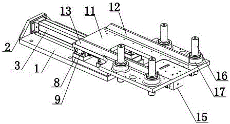
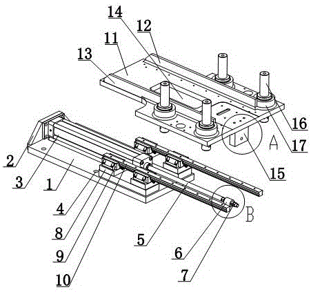
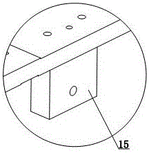
[0017] like Figure 1 to Figure 4 As shown, a drawing board pushing device includes a base plate 1, a side plate 2 is provided on the side wall of the base plate 1, a cylinder 3 is provided on the base plate 1, a telescopic shaft 5 is provided at the front of the cylinder 3, and one end of the telescopic shaft 5 Connected with the cylinder 3, the other end of the telescopic shaft 5 is provided with a fixed cylinder 6, the end of the telescopic shaft 5 is provided with a lock nut 7, and the lock nut 7 is arranged at the outer end of the fixed cylinder 6; the bottom plate 1 is provided with several bases 8 , the base 8 is provided with a fixed seat...


PUM


Abstract

The invention discloses a wire drawing plate push device which comprises a bottom plate, wherein a side plate is arranged on a side wall of the bottom plate; a cylinder is arranged on the bottom plate; a telescopic shaft is arranged at the front part of the cylinder; one end of the telescopic shaft is connected with the cylinder; a fixing cylinder is arranged at the other end of the telescopic shaft; a locking nut is arranged at an end part of the telescopic shaft; the locking nut is arranged at the outer end of the fixing cylinder; a plurality of bases are arranged on the bottom plate; fixing bases are arranged on the bases; a guide track is arranged on the fixing bases; a moving plate is arranged above the bottom plate; the moving plate is arranged on the guide track; a first limiting plate is arranged on one side of the moving plate; a second limiting plate is arranged on the other side of the moving plate; a fixing block is arranged at the bottom of the moving plate; an end part of the telescopic shaft is connected with a fixing block. By adopting the wire drawing plate push device, a wire drawing plate can be placed on the moving plate, then the wire drawing plate can be conveniently clamped through the limiting plate, movement control on the wire drawing plate can be conveniently achieved, and the wire drawing plate can be conveniently pushed.

Description

technical field [0001] The invention relates to a punching device, in particular to a drawing board pushing device. Background technique [0002] Punching plate refers to the metal plate products with various shapes and holes on the surface, which are widely used in chemical machinery, pharmaceutical equipment, food and beverage machinery, etc. The existing punching plate is inconvenient to install, and it is inconvenient to push the punching plate. Contents of the invention [0003] The present invention mainly solves the technical problems existing in the prior art, and thus provides a wire drawing board that can be placed on the moving board, and the wire drawing board can be conveniently clamped through the limiting board, so as to facilitate the movement control of the wire drawing board, The drawing board pushing device is convenient for pushing the drawing board. [0004] Above-mentioned technical problem of the present invention is mainly solved by following tech...

Claims


Application Information

Patent Timeline
IPC IPC(8): B21D45/00
CPCB21D45/003
Inventor 刘旭玲
Owner ZHEJIANG BANGXIANG CHEM FIBER CO LTD
Why Eureka
Try Eureka