
Environmental protection device

The technology of an environmental protection device and a blowing device is applied in the directions of drying gas arrangement, dryers, animal houses, etc., which can solve the problems of easy knotting, large space occupation and long operation time, etc., and improve space utilization. efficiency, reduce floor space and improve work efficiency

Active Publication Date: 2017-06-13
日照市双驱机械制造有限公司
View PDF4 Cites 10 Cited by
  • Summary
  • Abstract
  • Description
  • Claims
  • Application Information

AI Technical Summary

Problems solved by technology

[0002] At present, the aquaculture industry is developing at its peak, which brings huge economic benefits and more farmers join the aquaculture industry. However, regular cleaning and deodorization of the pollutants in the breeding pen is to ensure the normal growth and environmental protection of the animals. Important measures, the existing farmers generally use external water pipes to flush the pollutants in the breeding pens. However, because the water pipes have a certain length, it is very inconvenient to take and place, which makes the operation time longer and easy to put away. Knots appear, and at the same time, it is difficult to store the recycled water pipes, and it takes up a lot of space, which brings inconvenience to users, has great disadvantages, and needs to be improved

Method used


Image

  • Environmental protection device
  • Environmental protection device
  • Environmental protection device

Examples


Embodiment Construction

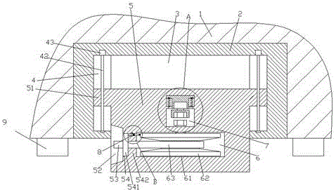
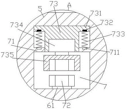
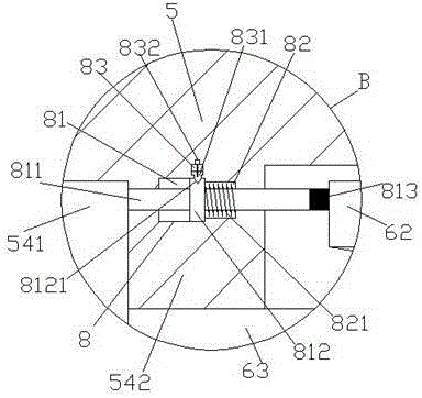
[0021] Such as Figure 1-Figure 6 As shown, an environmental protection device of the present invention includes a body 1 and a base 2 disposed in the body 1, and the bottom surface of the body 1 on the left and right sides of the base 2 is provided with a blowing device 9. The blowing device 9 is used to quickly dry the ground after cleaning, so as to prevent the moisture from causing damage to the rearing animals. The inner bottom of the base 2 is provided with an empty groove 3, and a sliding joint 5 is provided in the empty groove 3. The outer wall on the left side of the sliding joint 5 is provided with a pick-and-place area 52, the sliding joint 5 on the right side of the pick-and-place area 52 is provided with a connecting groove 54, and the sliding joint 54 on the right side of the installing groove 54 is 5 is provided with a first transfer cavity 6, and a first stopper 542 is provided between the first transfer cavity 6 and the connecting groove 54, and the sliding co...


PUM


Abstract

The invention discloses an environmental protection device. The environmental protection device comprises a device body and a base arranged in the device body, wherein the bottom end faces of the device body on the left side and the right side of the base are provided with air blowing devices; an empty groove is formed at the bottom in the base; a sliding connection piece is arranged in the empty groove; a taking and placing area is formed in the outer wall of the left side of the sliding connection piece; a mounting groove is formed in the sliding connection piece on the right side of the taking and placing piece; a first adaption cavity is formed in the sliding connection piece on the right side of the mounting groove; a first check block is arranged between the first adaption cavity and the mounting groove; a second adaption cavity is formed in the sliding connection piece above the first adaption cavity; the first check block is arranged in the second adaption cavity; a convex part is arranged in the second adaption cavity above the first check block; the tops of the two sides of the convex part are provided with convex shafts; magnetic blocks are arranged in the bottoms of the convex shafts; the top of the first check block corresponding to the magnetic blocks is provided with electromagnetic coil devices; first elastic pieces are arranged between the electromagnetic coil devices and the magnetic blocks; the bottom of the convex part passes through the first check block. The environmental protection device has a simple structure, and is convenient to operate; automatic storage of a water tube can be realized, the floor area is small, and the cleaning and deodorizing efficiency is increased.

Description

technical field [0001] The invention relates to the technical field of environmental protection, in particular to an environmental protection and deodorization device for breeding pens. Background technique [0002] At present, the aquaculture industry is developing at its peak, which brings huge economic benefits and more farmers join the aquaculture industry. However, regular cleaning and deodorization of the pollutants in the breeding pen is to ensure the normal growth and environmental protection of the animals. Important measures, the existing farmers generally use external water pipes to flush the pollutants in the breeding pens. However, because the water pipes have a certain length, it is very inconvenient to take and place, which makes the operation time longer and easy to put away. The phenomenon of knotting occurs, and at the same time, it is difficult to store the recycled water pipes, and it takes up a lot of space, which brings inconvenience to users, has great...

Claims


Application Information

Patent Timeline
Patent Type & Authority Applications(China)
IPC IPC(8): B08B3/02B08B13/00F26B21/00A01K1/01
CPCA01K1/01B08B3/02B08B13/00F26B21/00
Inventor 柯步勋
Owner 日照市双驱机械制造有限公司
Learn More