Mouth ring fixed connection structure of multistage centrifugal pump and quick detaching method for mouth ring fixed connection structure

A technology for centrifugal pumps and mouth rings, which is applied to components, pumps, and pump elements of pumping devices for elastic fluids, and can solve the problem of difficulty in accommodating cylindrical pins and screws at the same time, limited axial size of the mouth ring of the pump body, and inability to Achieve accuracy and other issues, achieve the effect of improving connection accuracy and strength, dispersing stress, and improving positioning effect

Pending Publication Date: 2017-06-09
兰州兰泵有限公司
View PDF9 Cites 3 Cited by
  • Summary
  • Abstract
  • Description
  • Claims
  • Application Information

AI Technical Summary

Problems solved by technology

[0004] Option 1. The mouth ring of the split pump body is only connected by screws; this solution is simple, but the two halves are easily misaligned during processing, and the required accuracy cannot be achieved.
[0005] Option 2: Use ordinary cylindrical pins for positioning and screw connections; this solution meets the requirements of processing technology and can ensure both positioning and connection, but the axial size of the pump body mouth ring is limited and the space is small, so it is difficult to accommodate both cylindrical pins and screws
[0006] Utilizing the above two design schemes, the inner diameter d cylindricity of the mouth ring of the split-open pump body is much greater than 0.02mm, and there are obvious misalignment phenomena in the secondary assembly process, and the processed products are unqualified

Method used


Image

  • Mouth ring fixed connection structure of multistage centrifugal pump and quick detaching method for mouth ring fixed connection structure
  • Mouth ring fixed connection structure of multistage centrifugal pump and quick detaching method for mouth ring fixed connection structure
  • Mouth ring fixed connection structure of multistage centrifugal pump and quick detaching method for mouth ring fixed connection structure

Examples


Embodiment Construction

[0037] The present invention will be further described below in conjunction with the accompanying drawings.

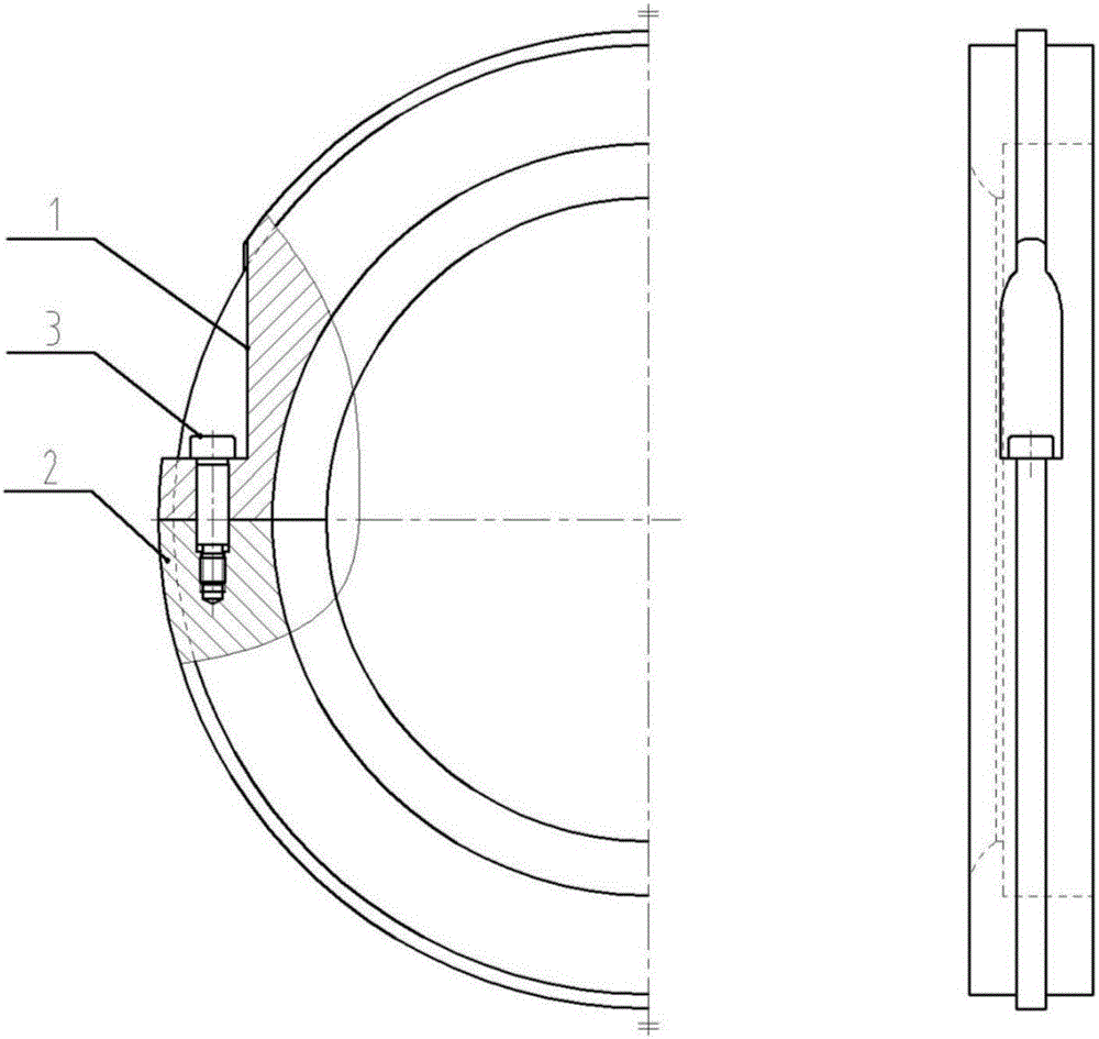
[0038] A multi-stage centrifugal pump mouth ring fixed connection structure, including the pump body upper mouth ring and the pump body lower mouth ring, the connection between the pump body upper mouth ring 1 and the pump body lower mouth ring 2 is provided with a connection hole, the connection hole Inner connection shoulder screw 3. A gap is provided on the upper mouth ring 1 of the pump body.

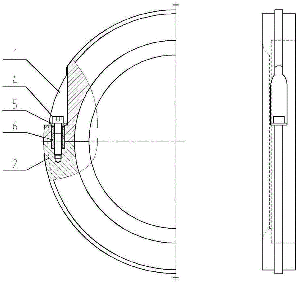
[0039] A connection hole is provided at the joint between the upper mouth ring 1 of the pump body and the lower mouth ring 2 of the pump body, and the hollow cylindrical pin 4 is connected in the connection hole. One end of the screw 5 passes through the hollow cylindrical pin 4 and is connected with the lower mouth ring 2 of the pump body. A flat washer 6 is arranged between the hollow cylindrical pin 4 and the cylindrical head screw 5 . The inner side of the hollow cyli...


PUM


Abstract

The invention relates to the technical field of hydraulic engineering design of pump bodies, in particular to a mouth ring fixed connection structure of a multistage centrifugal pump and a quick detaching method for the mouth ring fixed connection structure. The mouth ring fixed connection structure comprises a pump body upper mouth ring and a pump body lower mouth ring and is characterized in that a connecting hole is formed in a connected part of the pump body upper mouth ring and the pump body lower mouth ring; a shoulder screw is connected in the connecting hole; the shoulder screw is used, that is, the upper-half part of the shoulder screw is used for locating and the lower-half part of the shoulder screw is used for connecting. According to the scheme, the problem of insufficient space is solved; a gap is formed in the pump body upper mouth ring and is convenient for operation of mounting a tool; the connecting hole is formed in the connected part of the pump body upper mouth ring and the pump body lower mouth ring; a hollow cylindrical pin is connected in the connecting hole; threads are arranged on the inner side of the hollow cylindrical pin and are connected with an oval fillister head screw; one end of the oval fillister head screw penetrates through the hollow cylindrical pin and is connected with the pump body lower mouth ring; a clearance is further reduced.

Description

technical field [0001] The invention relates to the technical field of water conservancy design of a pump body, in particular to a fixed connection structure of a mouth ring of a multistage centrifugal pump and a quick disassembly method thereof. Background technique [0002] The pump body mouth ring of the multi-stage split centrifugal pump is a very important part, and the number of parts is large. In order to facilitate the installation, maintenance and replacement of the pump body mouth ring, the pump body mouth ring is usually designed as a split structure ( figure 1 ). This split-open pump body mouth ring has high precision requirements on the inner diameter d and outer diameter D, especially the inner diameter d requires the cylindricity to be within 0.02mm. If this requirement cannot be met, the pump body mouth ring and The rotor will produce eccentric wear, which will affect the normal operation of the pump and greatly shorten the life of the pump. Therefore, it i...

Claims


Application Information

Patent Timeline
Patent Type & Authority Applications(China)
IPC IPC(8): F04D29/62F04D29/42F04D1/06
CPCF04D1/06F04D29/426F04D29/628
Inventor 杨德旭张涛吴应德马文生马柏青张宏
Owner 兰州兰泵有限公司
Why Eureka
Try Eureka