
Reinforced yielding U-shaped steel bracket

A technology of steel support and section steel, applied in wellbore lining, tunnel lining, underground chamber, etc., can solve the problems of collapse, roadway collapse, rigid damage of supporting steel frame, etc., to ensure effective support and avoid buckling effect.

Active Publication Date: 2017-06-09
ANHUI UNIV OF SCI & TECH
View PDF5 Cites 5 Cited by
  • Summary
  • Abstract
  • Description
  • Claims
  • Application Information

AI Technical Summary

Problems solved by technology

[0002] In the process of roadway construction, in order to support the rock wall of the roadway, supporting steel frames are generally arranged in the roadway, and the supporting steel frames are mostly truss structures to support the top and waist of the roadway rock wall, avoid The problem of roadway collapse caused by the pressure release of the surrounding rock at the top and waist of the roadway. During the construction of the roadway, the surrounding rock pressure on the arc-shaped top of the roadway is applied to the supporting steel frame, and the surrounding rock pressure on the arc-shaped top of the roadway is released and transmitted to both sides of the waist of the roadway, thereby exerting compressive stress on the waist of the supporting steel frame; a large number of roadway construction monitoring data show that if the surrounding rock pressure on the arc-shaped top of the roadway is released too quickly, the rigidity of the supporting steel frame will be damaged, resulting in Buckling, kicking, and collapse of the supporting steel frame, creating a significant safety hazard

Method used


Image

  • Reinforced yielding U-shaped steel bracket
  • Reinforced yielding U-shaped steel bracket
  • Reinforced yielding U-shaped steel bracket

Examples


Embodiment Construction

[0023] combine Figure 1 to Figure 8 , the present invention is further described:

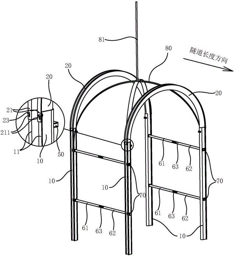
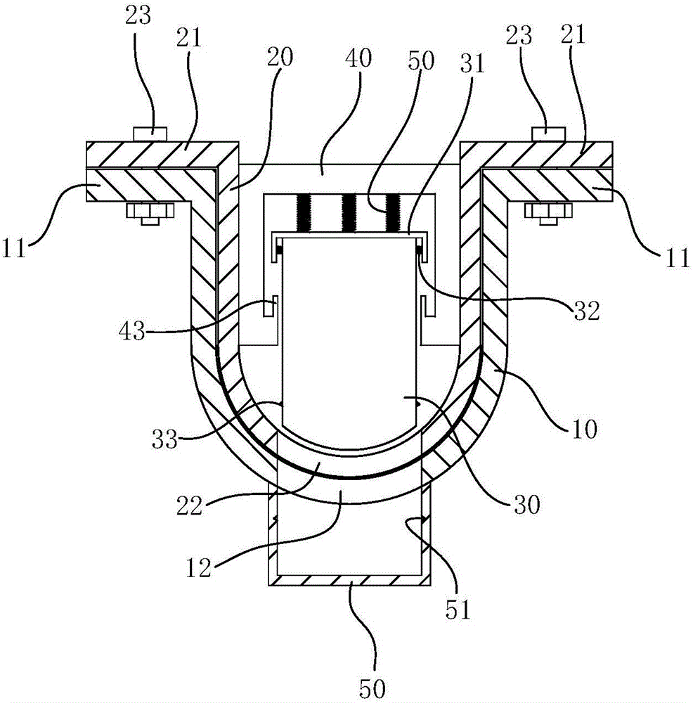
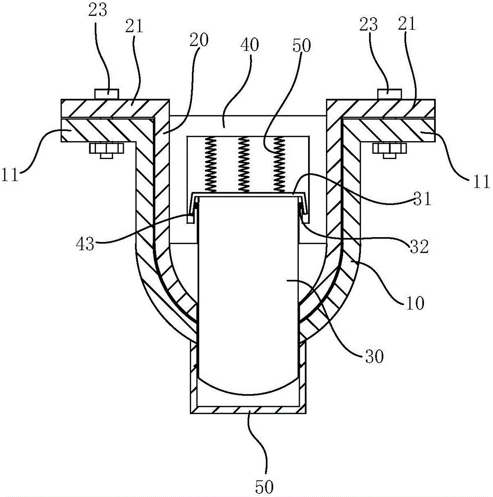
[0024] A reinforced U-shaped steel support that can be pressed, including first supporting steel 10 arranged vertically on both sides of the roadway, and the upper end of the first supporting steel 10 is provided with a second supporting rock for supporting the arc-shaped top of the roadway. Supporting shaped steel 20, the second supporting shaped steel 10, 20 is bent into a curved structure, the two ends of the second supporting shaped steel 20 respectively form a vertically movable fit with the upper end of the first supporting shaped steel 10, the second supporting shaped steel The two ends of the two supporting shaped steel 20 and the first supporting shaped steel 10 are provided with a limited slip pressure relief mechanism, which is used to block the downward movement of the second support shaped steel 20;

[0025] combine figure 1 As shown, the U-shaped steel supports of the above str...


PUM


Abstract

The invention relates to a reinforced yielding U-shaped steel bracket which comprises first support section steel vertically arranged on two sides of a roadway, wherein second support section steel for supporting surrounding rocks at the cambered top of the roadway is arranged at the upper ends of the first support section steel, and is bent into a curved structure; two ends of the second support section steel are movably matched with the upper ends of the first support section steel in the vertical direction respectively; slip limiting yielding mechanisms for stopping the second support section steel moving downwards are arranged at the overlapping parts of the first and second support section steel. Such yielding U-shaped steel brackets can be arranged at intervals in the length direction of the roadway, and the pressure of the surrounding rocks at the top of the roadway is released and transmitted to the second support section steel, so that a sufficient yielding amount is provided for the surrounding rocks at the top of the roadway to avoid the condition that the U-shaped steel brackets reach the yield strength to cause buckling, kicking and collapsing of the U-shaped steel brackets, and further ensure effective support to the surrounding rocks at the cambered top of the roadway, and yielding pressure release and rigid support of the surrounding rocks at the cambered top of the roadway are realized.

Description

technical field [0001] The invention relates to the technical field of roadway construction, in particular to a reinforced U-shaped steel bracket that can be compressed. Background technique [0002] In the process of roadway construction, in order to support the rock wall of the roadway, supporting steel frames are generally arranged in the roadway. The problem of roadway collapse caused by the pressure release of the surrounding rock at the top and waist of the roadway. During the construction of the roadway, the surrounding rock pressure on the arc-shaped top of the roadway is applied to the supporting steel frame, and the surrounding rock pressure on the arc-shaped top of the roadway is released and transmitted. to both sides of the waist of the roadway, thereby exerting compressive stress on the waist of the supporting steel frame; a large number of roadway construction monitoring data show that if the surrounding rock pressure at the arc-shaped top of the roadway is re...

Claims


Application Information

Patent Timeline
IPC IPC(8): E21D11/18E21D11/28
CPCE21D11/18E21D11/28
Inventor 张金松黄金坤何壮志严旺方冉徐敏姚兆龙王秀婷
Owner ANHUI UNIV OF SCI & TECH
Learn More