
Permanent plate pile underground structure and construction method thereof

A technology of underground structure and construction method, applied in foundation structure engineering, sheet pile walls, excavation, etc., can solve problems such as damage and poor water-stop effect, and achieve the effects of improving earthquake resistance, saving construction costs, and optimizing internal structures

Active Publication Date: 2017-06-09
JIANGSU DONGHENAN GEOTECHNICAL TECH CO LTD +1
View PDF3 Cites 5 Cited by
  • Summary
  • Abstract
  • Description
  • Claims
  • Application Information

AI Technical Summary

Problems solved by technology

However, the water-stopping effect of existing reinforced concrete sheet piles is worse than that of other pile structures, and after the excavation of the foundation pit is completed, the foundation pit support system will be To be dismantled, because the support system uses a large number of steel members or reinforced concrete members, and these members are at least partly fixedly connected with the reinforced concrete sheet piles, when the support system is removed, it will inevitably cause damage to the structure of the reinforced concrete sheet piles. destroy

Method used


Image

  • Permanent plate pile underground structure and construction method thereof
  • Permanent plate pile underground structure and construction method thereof
  • Permanent plate pile underground structure and construction method thereof

Examples


Embodiment 1

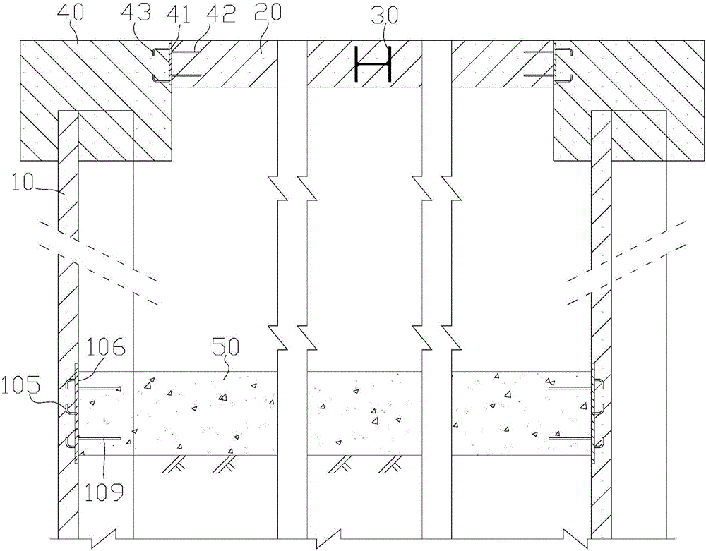
[0042] see figure 1 , figure 2 and image 3 , a permanent sheet pile underground structure, comprising:

[0043] A sheet pile wall 10 formed of interconnected reinforced concrete corrugated sheet piles 1 as the outer wall of the permanent sheet pile underground structure; a crown beam 40 arranged on top of the sheet pile wall 10; supported on The horizontal support beam 30 on the inner side of the crown beam 40; the roof 20 with the horizontal support beam 30 as a structural beam; the reinforced concrete bottom plate 50 connected to the inner side of the sheet pile wall 10;

[0044] The sheet pile wall 10 is the support structure of the foundation pit of the permanent sheet pile underground structure; the crown beam 40 and the horizontal support beam 30 are the crown beam and the support system of the foundation pit of the permanent sheet pile underground structure. Horizontal support beams.

[0045] In this embodiment, the horizontal support beam is a steel beam made of ...

Embodiment 2

[0056] The structure of this embodiment is basically the same as that of Embodiment 1, the difference is that the opening direction of the groove of the main body of the reinforced concrete corrugated sheet pile faces the direction outside the foundation pit, please refer to Figure 6 , Figure 6 It is a schematic diagram of a sheet pile wall 60 forming an underground structure using a reinforced concrete wave sheet pile 6, wherein the opening direction of the groove of the main body of the reinforced concrete wave sheet pile 6 faces the direction outside the foundation pit. The structure of reinforced concrete wave sheet pile 6 is similar to that of reinforced concrete wave sheet pile 1, see Figure 7 The reinforced concrete wave sheet pile 6 includes a main body 601 with a U-shaped cross section. The main body 601 is a reinforced concrete structure, which is specifically formed by concrete 602 and stirrups 603 and longitudinal bars 604 wrapped inside the concrete 602. A part...

Embodiment 3

[0064] This embodiment is a construction method for constructing the permanent sheet pile underground structure described in Embodiment 1, which specifically includes the following steps:

[0065] (1) Please refer to Figure 9 In step a, the guide groove 71 is excavated along the edge of the foundation pit to be excavated, Figure 9 The middle mark 200 represents the ground;

[0066] (2) See Figure 9 In the b step, the reinforced concrete corrugated sheet pile is sunk and reaches the set depth, so that the adjacent reinforced concrete corrugated sheet piles are engaged with each other to form the sheet pile wall 10; the reinforced concrete corrugated sheet pile used in this embodiment is Figure 4 The shown reinforced concrete corrugated sheet pile 1, the specific structure of the reinforced concrete corrugated sheet pile 1 please refer to Figure 4 And the description in embodiment 1, no longer repeat;

[0067] A steel pre-embedded slab is provided on the inner side of t...


PUM


Abstract

The invention discloses a permanent plate pile underground structure. The permanent plate pile underground structure comprises a plate pile wall formed by reinforced concrete corrugated plate piles which are mutually connected, a crown beam arranged on the top of the plate pile wall, a horizontal supporting beam supporting the inner side of the crown beam, a top plate with the horizontal supporting beam as a structural beam, and a reinforced concrete bottom plate connected to the inner side face of the plate pile wall, wherein the plate pile wall serves as an outer wall of the underground structure and is a supporting structure of a foundation trench of the underground structure, and the crown beam and the horizontal supporting beam serve as a crown beam and a horizontal supporting beam of a supporting system of the foundation trench of the permanent plate pile underground structure. The invention further discloses a construction method of the underground structure. According to the permanent plate pile underground structure, the crown beam and the horizontal supporting beam in the supporting system of the foundation trench are remained, the crown beam and the horizontal supporting beam serve as a frame structure of the top plate of the underground structure, the dismounting construction period of the crown beam and the horizontal supporting beam is saved, the building expenditure of the top plate of the underground structure is saved, and meanwhile the anti-seismic performance of the top plate of the underground structure is improved.

Description

technical field [0001] The invention relates to an underground building structure and a construction method for the underground building structure, in particular to a permanent sheet pile underground structure and a construction method thereof. Background technique [0002] During the construction of underground buildings, foundation pits should be dealt with in some areas where slope grading is not suitable for foundation pit excavation, and when it may cause harm to adjacent buildings or structures, underground pipelines or large main traffic arteries. Support. [0003] In addition to the natural soil and water pressure of the soil around the foundation pit, the support structure of the foundation pit mainly bears the earth pressure caused by the unloading of the excavation of the soil in the foundation pit during the excavation process of the foundation pit. These pressures are transmitted to the support, and the support structure and support members together form the su...

Claims


Application Information

Patent Timeline
IPC IPC(8): E02D5/10E02D5/14E02D17/04E02D31/02
CPCE02D5/10E02D5/14E02D17/04E02D31/02
Inventor 李仁民谢鹏王建兰王涛
Owner JIANGSU DONGHENAN GEOTECHNICAL TECH CO LTD
Learn More