Electrolytic Capacitorless Power Converter and Control Method for Permanent Magnet Synchronous Motor Drive System

A permanent magnet synchronous motor and power converter technology, which is used in AC motor control, conversion of DC power input to DC power output, and conversion of AC power input to AC power output, etc. Poor power quality, failure of electrolytic capacitors, etc., to achieve high-performance operation, improve power quality, and improve average voltage

Active Publication Date: 2018-12-14
JIANGSU UNIV
View PDF5 Cites 0 Cited by
  • Summary
  • Abstract
  • Description
  • Claims
  • Application Information

AI Technical Summary

Problems solved by technology

However, the service life of electrolytic capacitors is only 8000 hours (85°C), and decreases rapidly as the operating temperature increases, resulting in a decrease in the life and reliability of the motor drive system
According to literature records, 60% of voltage source inverter failures are caused by the failure of electrolytic capacitors.
To solve this problem, long-life, high-reliability film capacitors are generally used instead of electrolytic capacitors. However, due to cost constraints, the motor drive system can only use low-capacity film capacitors, which cannot effectively absorb the pulsating power of the grid. DC There are large fluctuations in the bus voltage, resulting in an increase in the output power and torque ripple of the motor, which seriously reduces the dynamic and static performance of the motor, and limits the application of the electrolytic capacitor power converter in the field of motor drive
At present, the existing non-electrolytic capacitor power converters based on Z-source inverters use Z-source networks to replace electrolytic capacitors with thin-film capacitors, but there are many devices, difficult manufacturing of inductors, complex control, and poor power quality on the grid side. Due to the disadvantages of large inertial loads; the step-up active power decoupling circuit can realize the power balance of the motor drive system, but the increase of the bus voltage increases the cost of the three-phase inverter
Parallel connection of power processing circuits on the DC bus can reduce bus voltage fluctuations when the grid voltage is low, but there are disadvantages of low power factor at the grid side and large current harmonic content

Method used


Image

  • Electrolytic Capacitorless Power Converter and Control Method for Permanent Magnet Synchronous Motor Drive System
  • Electrolytic Capacitorless Power Converter and Control Method for Permanent Magnet Synchronous Motor Drive System
  • Electrolytic Capacitorless Power Converter and Control Method for Permanent Magnet Synchronous Motor Drive System

Examples


Embodiment Construction

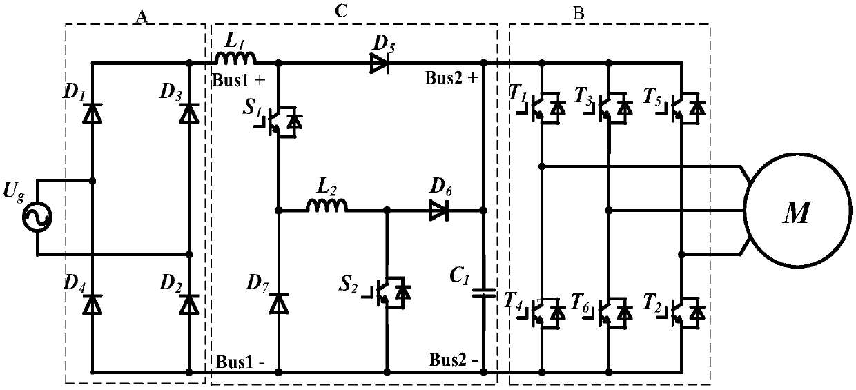
[0022] Such as figure 2 As shown, the non-electrolytic capacitor power converter of the permanent magnet synchronous motor drive system proposed by the present invention includes a single-phase rectifier circuit unit A, an active power buffer circuit C, and a three-phase inverter B. The input terminal of single-phase rectifier circuit unit A and the grid U g Connected, the anode of the output terminal of the single-phase rectifier circuit unit A is connected to the anode of the active power buffer circuit C, and the cathode of the output terminal of the single-phase rectifier circuit unit A is connected to the cathode of the active power buffer circuit C and the cathode of the three-phase inverter B . The positive pole of the input terminal of the three-phase inverter B is connected to the positive pole of the output terminal of the active power buffer circuit C, and the output terminal of the three-phase inverter B is connected to the three-phase winding of the permanent magne...


PUM


Abstract

The invention discloses a permanent magnet synchronous motor drive system non-electrolytic capacitor power converter and a control method in the field of power electronics. , the second inductance, the film capacitor, the fifth diode, the sixth diode, the seventh diode and the first and second switching tubes are composed of an active power buffer circuit, and the active power buffer circuit is used to control the grid output The current tracks the voltage change of the grid. When the output power of the grid is greater than the input power of the motor, the grid directly supplies power to the motor through the three-phase inverter. The active power buffer circuit absorbs the excess pulsating energy of the grid. The source power buffer circuit releases energy for the motor to work. Under the premise of ensuring the motor's operating performance, the power factor of the grid side is approximately 1, and the harmonic output current of the grid is lower than 5%, which improves the service life of the drive system.

Description

Technical field [0001] The invention belongs to the technical field of power electronics, and relates to a power converter used in a permanent magnet synchronous motor drive system and a control method thereof. Background technique [0002] Permanent magnetic synchronous motor (PMSM) has the advantages of simple structure, high power density, and convenient maintenance. It has gradually replaced DC brushed motors and asynchronous motors in the fields of household appliances, industrial production, and automobile drives. At present, the drive system of PMSM generally uses attached figure 1 The voltage source inverter shown uses a large capacitance electrolytic capacitor to absorb the pulsating power of the grid to stabilize the DC bus voltage and achieve high-performance motor operation. However, the service life of electrolytic capacitors is only 8000 hours (85°C), and it drops rapidly as the operating temperature increases, resulting in a decrease in the service life and reliabi...

Claims


Application Information

Patent Timeline
Patent Type & Authority Patents(China)
IPC IPC(8): H02M5/458H02M1/34H02J3/01H02P6/10H02P27/06
CPCH02J3/01H02M1/34H02M5/458H02P6/10H02P27/06H02M1/344H02M1/15H02M3/1582
Inventor 张超王琨朱孝勇全力杜怿左月飞
Owner JIANGSU UNIV
Why Eureka
Try Eureka