
A motor stator chip precision forming machine

A technology for motor stators and molding machines, applied in the manufacture of stator/rotor bodies, etc., can solve problems affecting chip quality and uneven stator chips, and achieve the effects of improved quality, convenient operation, and simple structure

Inactive Publication Date: 2018-10-26
望江县雷创科技有限公司
View PDF6 Cites 0 Cited by
  • Summary
  • Abstract
  • Description
  • Claims
  • Application Information

AI Technical Summary

Problems solved by technology

[0003] Most of the existing stator molding is to form the stator blank of the stator chip first, and the stator blank of the stator chip is formed into a circular ring, the inner and outer diameters of which are the same as the iron chip, and then the inner circular hole of the stator chip is used to position the groove and use it. For the superposition positioning between chips, this method of positioning only on the circular surface is equivalent to only positioning the inner circular hole of each iron chip, ignoring the eccentricity of the iron chip during the casting process, which will cause As a result, the outside of the formed stator chip is uneven, which affects the quality of the chip

Method used


Image

  • A motor stator chip precision forming machine
  • A motor stator chip precision forming machine
  • A motor stator chip precision forming machine

Examples


Embodiment Construction

[0031] In order to enable those skilled in the art to better understand the technical solution of the present invention, the present invention will be described in detail below in conjunction with the accompanying drawings. The description in this part is only exemplary and explanatory, and should not have any limiting effect on the protection scope of the present invention. .

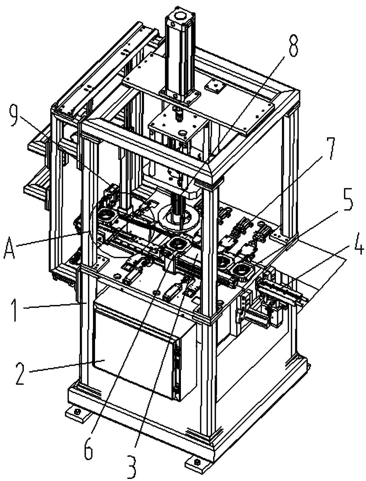
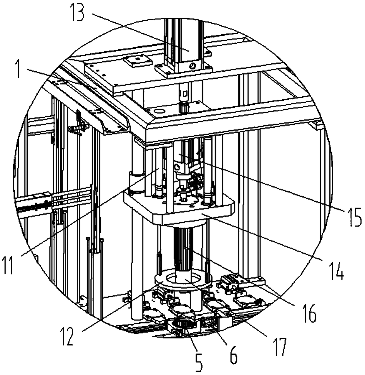
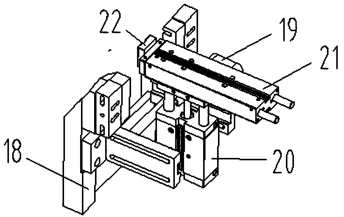
[0032] Such as Figure 1-Figure 8As shown, the specific structure of the present invention is: a precision molding machine for motor stator chips, which includes a frame 1 and a power distribution control box 2, and the frame 1 is provided with a conveying groove 3 that cooperates with a chipset 5, The conveying trough 3 is equipped with a feeding device 6, and a molding device 8 that cooperates with the chipset 5 is provided above the middle of the conveying trough 3, and the forming device 8 includes an outer ring positioning cylinder arranged on the frame 1 11 and forming lifting cylinder 13, the o...


PUM


Abstract

The invention relates to an accurate molding machine of a stator chip of a motor. The accurate molding machine comprises a rack and a power distribution control box, wherein the rack is provided with a conveying groove matched with a chip group; the conveying groove is matched with a feeding device; a molding device matched with the chip group is arranged above the middle of the conveying groove; the molding device comprises an outer ring positioning air cylinder and a molding hoisting air cylinder which are arranged on the rack; the lower side of the outer ring positioning air cylinder is connected with an outer ring positioning sleeve matched with the outer side of the chip group; the lower side of the molding hoisting air cylinder is connected with a molding hoisting seat; the molding hoisting seat is connected with a molding groove pressing head; the lower side of the molding groove pressing head is in sleeve joint with an inner hole positioning head; the molding groove pressing head sleeves the inner hole positioning head through a resetting spring; and the inner hole positioning head is matched with an inner round hole of the chip group. The accurate molding machine provided by the invention realizes all-directional positioning; meanwhile, the inner hole positioning head can be pressed into the molding groove pressing head, and the effect, caused by the groove pressing head, on groove pressing on the inner side of the chip is not influenced; and the molding quality is ensured, and the appearance of the stator chip is guaranteed.

Description

technical field [0001] The invention relates to the field of electronic stator processing equipment, in particular to a precision molding machine for motor stator chips. Background technique [0002] During the processing of the stator chip, most of the stator chips need to be formed, and there are many methods for forming the stator chip. [0003] Most of the existing stator molding is to form the stator blank of the stator chip first, and the stator blank of the stator chip is formed into a circular ring, the inner and outer diameters of which are the same as the iron chip, and then the inner circular hole of the stator chip is used to position the groove and use it. For the superposition positioning between chips, this method of positioning only on the circular surface is equivalent to only positioning the inner circular hole of each iron chip, ignoring the eccentricity of the iron chip during the casting process, which will cause As a result, the outside of the formed s...

Claims


Application Information

Patent Timeline
Patent Type & Authority Patents(China)
IPC IPC(8): H02K15/02
CPCH02K15/02
Inventor 邓君徐红娇何楚亮
Owner 望江县雷创科技有限公司
Learn More