Eureka AIR delivers breakthrough ideas for toughest innovation challenges, trusted by R&D personnel around the world.

SOC optimal dropping factor control method applied to distributed energy storage system

A distributed energy storage and control method technology, applied in the field of distributed energy storage system load current distribution, can solve the problems of accelerated aging of energy storage units, failure to respond to the SOC information of energy storage units, etc., and achieve the effect of improving support capacity

Active Publication Date: 2017-05-31
YANSHAN UNIV
View PDF5 Cites 8 Cited by
  • Summary
  • Abstract
  • Description
  • Claims
  • Application Information

AI Technical Summary

Problems solved by technology

The traditional droop control fixes the droop coefficient as a constant when performing load distribution, so it cannot reflect the SOC information of the energy storage unit, and long-term operation leads to accelerated aging of the energy storage unit, which cannot maximize the advantages of the energy storage unit

Method used


Image

  • SOC optimal dropping factor control method applied to distributed energy storage system
  • SOC optimal dropping factor control method applied to distributed energy storage system
  • SOC optimal dropping factor control method applied to distributed energy storage system

Examples


Embodiment Construction

[0034] The present invention will be further described below in conjunction with accompanying drawing:

[0035] Method steps of the present invention are as follows:

[0036] Step 1. Construct the optimal droop factor of the SOC; the control block diagram of the optimal droop factor control of the SOC, such as figure 1 Shown:

[0037] Step 1.1, constructing the optimal droop factor of SOC, its transfer function G(soc) is, the algorithm is as follows:

[0038]

[0039] where k D is a proportional coefficient; p is a constant; i dc Output current for the port; A soc n for soc n mean; soc n is the nth power of soc;

[0040] Step 1.2, the influence of the parameter change of the SOC optimal droop factor on the system is as follows:

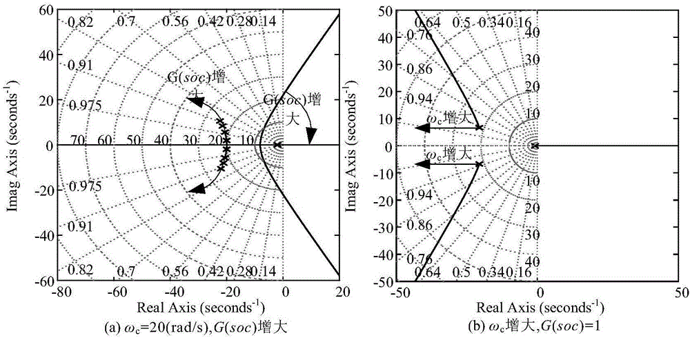
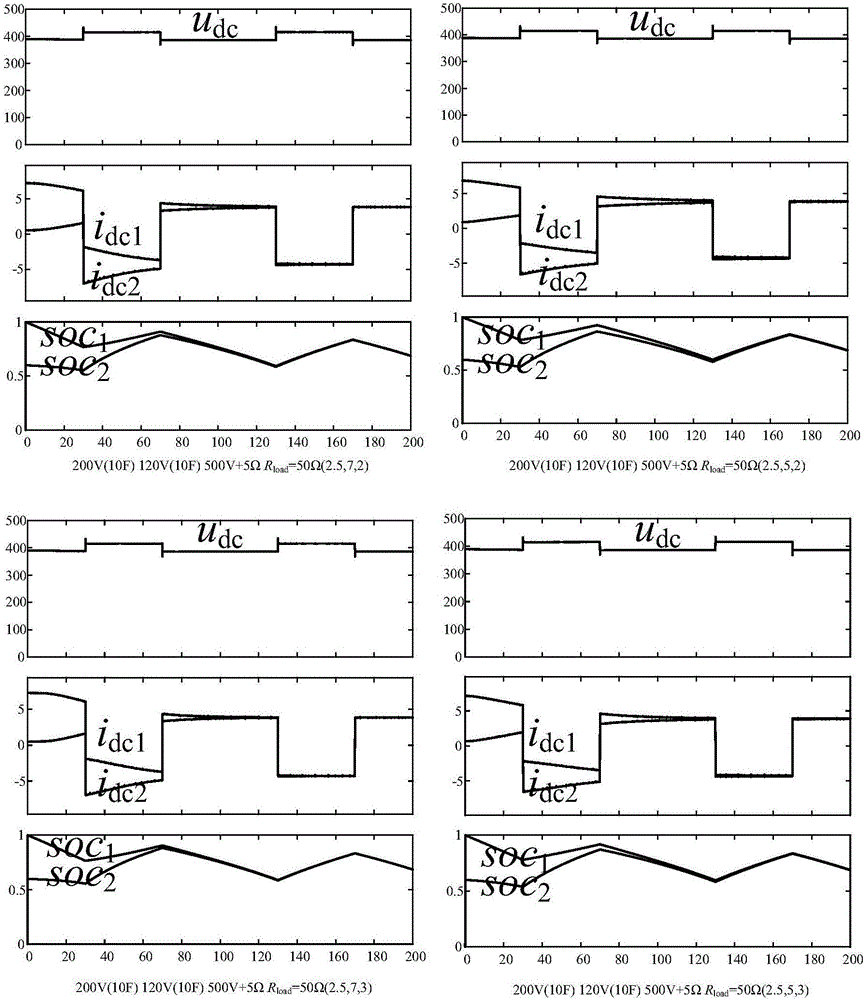
[0041] Parameter k in SOC optimal droop factor D , p, n select different values ​​respectively, and the corresponding root locus diagram is shown in the attached figure 2 shown.

[0042] Parameter k in SOC optimal droop factor D is th...


PUM


Abstract

The invention discloses an SOC optimal dropping factor control method applied to a distributed energy storage system. The SOC optimal dropping factor control method comprises the following steps: step one, constructing an SOC optimal dropping factor; step two, describing a control system into a voltage source type converter according to the topological structure of a distributed energy storage converter; step three, comparing the product of the dropping factor and output port current idc with output end reference voltage udc, and forming new dropping control reference voltage u*dc; step four, designing a voltage and current adjuster, so that the phase margin and amplitude margin of the voltage and current adjuster are large enough; and step five, adding secondary control to compensate busbar voltage dropping, so that the whole system has relatively high dynamic response and relatively small steady-state error. The load can be effectively distributed according to surplus capacities of a storage battery and a supercapacitor through the SOC optimal dropping factor concluded through simulation and experiments, so that SOC quickly trends to be coincident, and the load trends to be equal. The SOC and port voltage information are shared through an interconnecting wire, and the method is used for dropping factor self-adaptive adjustment and busbar voltage recovery.

Description

technical field [0001] The invention relates to the technical field of regulator application, in particular to a load current distribution method suitable for distributed energy storage systems. Background technique [0002] For renewable energy power generation based on DC bus, due to the unstable output power of renewable energy and the resistance of low-voltage lines, it is necessary to increase the reliability and stability of the system by adding energy storage units, and at the same time, the influence of line impedance needs to be considered. The traditional droop control fixes the droop coefficient as a constant when performing load distribution, so it cannot reflect the SOC information of the energy storage unit. Long-term operation will lead to accelerated aging of the energy storage unit, and the advantages of the energy storage unit cannot be maximized. [0003] The actual energy storage unit has a large capacity, so the SOC does not change significantly in a sho...

Claims


Application Information

Patent Timeline
Patent Type & Authority Applications(China)
IPC IPC(8): H02J3/32
CPCH02J3/32
Inventor 张纯江李鹏程阚志忠
Owner YANSHAN UNIV
Why Eureka
Eureka Blog
Learn More