Protected cable terminal fastener

A cable termination and fastener technology, which is applied in the direction of connecting/terminating cable equipment, etc., can solve the problems of the cable itself, such as large elasticity, increased difficulty, bounce or slip, etc., to achieve good stability and save operation difficulty.

Inactive Publication Date: 2017-05-31
GUANGZHOU PANYU CABLE WORKS
View PDF7 Cites 0 Cited by
  • Summary
  • Abstract
  • Description
  • Claims
  • Application Information

AI Technical Summary

Problems solved by technology

[0002] It is very important to ensure the safe and stable operation of the power grid in today's society. The cable is erected on the pole or building through the street yard. The fixing of the cable end is generally to bend the cable end around the street yard and then bend it Under tension, bind or fix the bent cable ends; at present, construction workers usually use traditional methods such as manpower or simple tools to bend the cable ends and use binding wires to bind and fix the bent cable ends. Because the diameter of the cable is relatively thick, it is difficult for personnel working at heights to bend and tighten the cable only by manpower or simple tools, and the cable itself is very elastic when it is bent, and it is easy to bounce or slip off from the hands or simple tools. Increased the difficulty of construction

Method used


Image

  • Protected cable terminal fastener
  • Protected cable terminal fastener

Examples


Embodiment Construction

[0015] A protective cable terminal fastener of the present invention will be further described below in conjunction with the accompanying drawings:

[0016] It should be noted that the terms "upper", "lower", "front", "rear" and similar expressions used in this specification are only for the purpose of illustration, and are determined according to the actual situation in the embodiment.

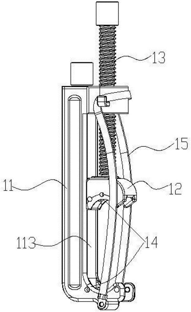
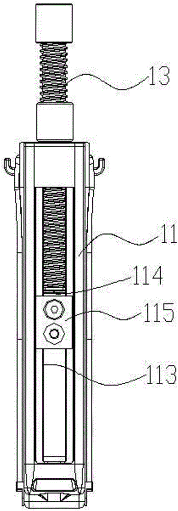
[0017] Such as Figure 1-2 As shown, a protective cable terminal fastener includes a crimping body 11, a dynamic pressure block 12, a crimping screw 13 and a protective belt 15. The top and bottom of the crimping body 11 are oppositely arranged, and the dynamic pressure block 12 is located Between the top and the bottom of the line body 11 and opposite to the bottom, the bottom of the line body 11 and the lower surface of the dynamic pressure block 12 are respectively provided with clamping structures 14 for clamping cables, and the compression screw 13 passes through vertically and is thread...


PUM


Abstract

The invention discloses a protected cable terminal fastener. The protected cable terminal fastener comprises a compression line body, a dynamic pressure block, a fastening screw rod and a protective belt. The dynamic pressure block is arranged between the top of the compression line body and the bottom of the compression line body and is opposite to the bottom. Wire-clamping structures for matching and clamping cables are respectively arranged on the bottom of the compression line body and the lower surface of the dynamic pressure block. The fastening screw rod passing through the top of the compression line body vertically is connected with the top of the compression line body in screwing mode. The lower end of the fastening screw rod is connected with the dynamic pressure block in rotation mode. The reciprocating motion of the dynamic pressure block relative to the bottom of the compression line body can be adjusted by rotating the fastening screw rod. A stop gear used for limiting the dynamic pressure block to prevent the dynamic pressure block from rotating relative to the bottom of the compression line body is arranged on the compression line body. The protective belt is disposed in two sides of the compression line body respectively. The two ends of the protective belt are connected with the top and the bottom of the compression line body respectively. The protected cable terminal fastener is labor-saving, can bend and compress cables round street codes and porcelain insulators together rapidly and save operative difficulty index by the protective belt that prevents cables from breaking away and bears the weight of the fastener.

Description

technical field [0001] The invention relates to the field of power tools, in particular to a protective cable terminal fastener. Background technique [0002] It is very important to ensure the safe and stable operation of the power grid in today's society. The cable is erected on the pole or building through the street yard. The fixing of the cable end is generally to bend the cable end around the street yard and then bend it Under tension, bind or fix the bent cable ends; at present, construction workers usually use traditional methods such as manpower or simple tools to bend the cable ends and use binding wires to bind and fix the bent cable ends. Because the diameter of the cable is relatively thick, it is difficult for personnel working at heights to bend and tighten the cable only by manpower or simple tools, and the cable itself is very elastic when it is bent, and it is easy to bounce or slip off from the hands or simple tools. Increased the difficulty of constructi...

Claims


Application Information

Patent Timeline
Patent Type & Authority Applications(China)
IPC IPC(8): H02G1/14
CPCH02G1/14
Inventor 胡超强尤占山孙建吉覃丹陈雪儿卢广业张开拓王延发张仕欢郝燕邵源鹏程雪丽
Owner GUANGZHOU PANYU CABLE WORKS
Why Eureka
Try Eureka