
Push-pull electric power drawer cabinet device

A drawer cabinet, push-pull technology, applied in the direction of pull-out switch cabinets, switchgear, electrical components, etc., can solve the problems of easy sliding of drawers, unfavorable installation or maintenance of power components, and reduction of installation or maintenance efficiency, etc. Simple structure, convenient installation or maintenance, and the effect of improving efficiency

Inactive Publication Date: 2017-05-31
广州冠松电力科技有限公司
View PDF5 Cites 0 Cited by
  • Summary
  • Abstract
  • Description
  • Claims
  • Application Information

AI Technical Summary

Problems solved by technology

The position of the traditional chest of drawers is generally movable when the drawer is pulled out, but when installing or overhauling power components in the drawer, it often produces a certain push and pull force on the drawer. It is beneficial to install or overhaul power components, and will greatly reduce the efficiency of installation or overhaul

Method used


Image

  • Push-pull electric power drawer cabinet device
  • Push-pull electric power drawer cabinet device
  • Push-pull electric power drawer cabinet device

Examples


Embodiment Construction

[0017] Combine below Figure 1-4 The present invention will be described in detail.

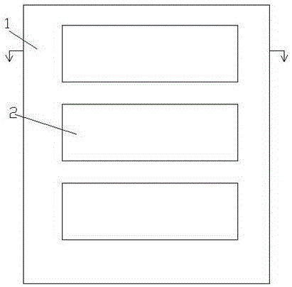
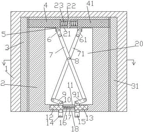
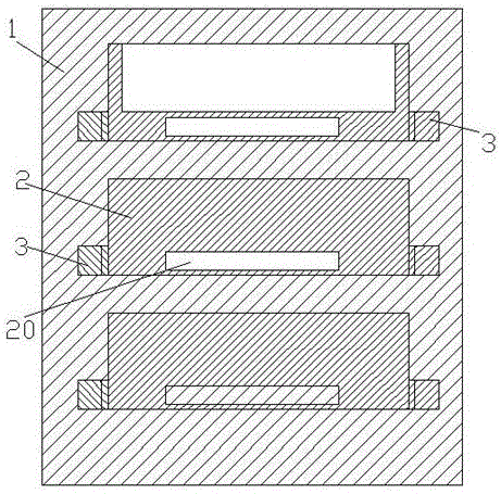
[0018] refer to Figure 1-4 , a push-pull electric power drawer device according to the present invention, comprising a cabinet body 1, a plurality of drawer slots arranged in the cabinet body 1 and separated up and down, and installed in the drawer slots for installing power components A plurality of drawer boxes 2, each drawer groove side wall middle and lower positions are symmetrically provided with a left fixing groove and a right fixing groove, and the left fixing groove and the right fixing groove are respectively fixedly equipped with a left rack 3 and a right rack 31. The lower end wall of each drawer box 2 is provided with an active slot 20, and the rear end wall of the active slot 20 is provided with a rear sliding slot, and the rear sliding slot is divided into a left rear sliding slot and a right rear sliding slot by a partition 22. Slot, the left rear sliding block 4 and the r...


PUM


Abstract

The invention discloses a push-pull electric power drawer cabinet device which comprises a cabinet, a plurality of drawer grooves and a plurality of drawer boxes. The drawer grooves are formed in the cabinet and are separated from one another in the up-down directions, the drawer boxes are mounted in the drawer grooves and are used for mounting electric power components, left fixing grooves and right fixing groove are symmetrically formed in the middle lower portions of two side walls of each drawer groove, left racks and right racks are respectively fixedly mounted in the left fixing grooves and the right fixing grooves, teeth are arranged on the end surfaces, which face the drawer grooves, of the left racks and the right racks, a movable groove is formed in the wall of the lower end of each drawer box, rear slide grooves are formed in the walls of the rear ends of the movable grooves and are divided into left rear slide grooves and right rear slide grooves by partition plates, and left rear sliders and right rear sliders are respectively slidably mounted in the left rear slide grooves and the right rear slide grooves.

Description

technical field [0001] The invention relates to the field of electric equipment, in particular to a push-pull electric drawer device. Background technique [0002] The power drawer is a common component in the field of power and electrical sensor control. The power drawer cabinet is used to install various sensors, controllers and other components for power control. In order to facilitate maintenance and installation, the power installation cabinet usually has drawers for pushing and pulling to maintain the components inside. [0003] Many drawers often need to be installed, and one of them needs to be pulled out during installation and maintenance. The position of the traditional chest of drawers is generally movable when the drawer is pulled out, but when installing or overhauling power components in the drawer, it often produces a certain push and pull force on the drawer. It is beneficial to install or overhaul power components, and will also greatly reduce the effici...

Claims


Application Information

Patent Timeline
Patent Type & Authority Applications(China)
IPC IPC(8): H02B11/127
CPCH02B11/127
Inventor 袁承宇
Owner 广州冠松电力科技有限公司
Learn More