
Broadband low-section omni-directional circularly polarized antenna

A circularly polarized antenna and low-profile technology, which is applied in the field of broadband low-profile omnidirectional circularly polarized antennas, can solve problems such as the narrow frequency band of omnidirectional circularly polarized antennas, and achieve increased antenna impedance and pattern bandwidth. Effect of axial ratio properties

Active Publication Date: 2017-05-31
GUILIN UNIV OF ELECTRONIC TECH
View PDF4 Cites 24 Cited by
  • Summary
  • Abstract
  • Description
  • Claims
  • Application Information

AI Technical Summary

Problems solved by technology

[0003] What the present invention is to solve is the problem that the frequency band of the existing omnidirectional circularly polarized antenna is relatively narrow, and a broadband low profile omnidirectional circularly polarized antenna is provided

Method used


Image

  • Broadband low-section omni-directional circularly polarized antenna
  • Broadband low-section omni-directional circularly polarized antenna
  • Broadband low-section omni-directional circularly polarized antenna

Examples


Embodiment Construction

[0032] The present invention is described in detail below in conjunction with accompanying drawing and specific embodiment, present embodiment is carried out under the premise of technical solution of the invention, has provided detailed embodiment and specific operation process, but protection scope of the present invention is not limited to the following Example. Based on the embodiments of the present invention, all other embodiments obtained by persons of ordinary skill in the art without making creative efforts belong to the protection scope of the present invention.

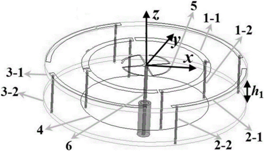
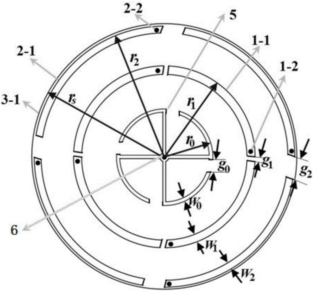
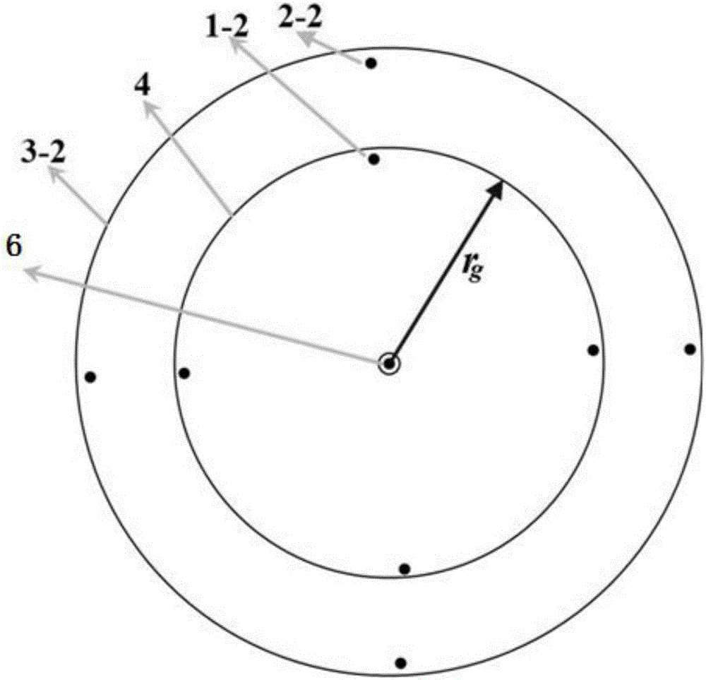
[0033] Broadband low-profile omnidirectional circularly polarized antennas, such as Figure 1-4 As shown, it consists of a zero-order resonator, a parasitic radiator, an upper dielectric substrate 3-1, a lower dielectric substrate 3-2, a metal floor 4, a radial feeding network 5 and a feeding probe 6.

[0034] The antenna has three dielectric layers, including an upper dielectric substrate 3-1 located on t...


PUM


Abstract

The invention discloses a broadband low-section omni-directional circularly polarized antenna. A dielectric substrate of the broadband low-section omni-directional circularly polarized antenna comprises an upper-layer dielectric substrate and a lower-layer dielectric substrate, the upper-layer dielectric substrate and the lower-layer dielectric substrate are parallel to each other, and the upper-layer dielectric substrate is positioned right above the lower-layer dielectric substrate; a metal floor is adhere on the lower-layer dielectric substrate; a zero-order resonator, a parasitic radiator and a radiation type feeding network are adhered on the upper-layer dielectric substrate; the radiation type feeding network is positioned in the center of the upper-layer dielectric substrate; zero-order resonant patches of the zero-order resonator are annularly on the outer side of the radiation type feeding network, one end of each zero-order resonant dowel of the zero-order resonator is connected with the corresponding zero-order resonant patch, and the other end of each zero-order resonant dowel is connected with the metal floor; parasitic radiation patches are annularly arranged on the outer sides of the zero-order resonant patches, one end of each parasitic radiation dowel of the corresponding parasitic radiation patch is connected with the corresponding parasitic radiation patch, and the other end of each parasitic radiation dowel is suspended. The broadband low-section omni-directional circularly polarized antenna has the advantages that impedance of the broadband low-section omni-directional circularly polarized antenna and the bandwidths of directional diagrams can be increased, and excellent axial ratio characteristics can be kept.

Description

technical field [0001] The invention relates to the technical field of omnidirectional circularly polarized antennas, in particular to a broadband low-profile omnidirectional circularly polarized antenna. Background technique [0002] Circularly polarized antennas are widely used because they can receive arbitrary polarized waves (and vice versa), left / right circularly polarized waves are orthogonal, radiated waves are rotationally symmetric, and can suppress cloud and rain interference and anti-multipath reflection. Circular polarization with omnidirectional radiation characteristics is more significant because it can achieve omnidirectional coverage. However, the current general omnidirectional circularly polarized antennas, such as helical dipole antennas, cylindrical conformal antenna arrays, back-to-back antennas, and monopole antennas, are all broad fire structures, so they need to be placed vertically and occupy a relatively large area. Large space, not suitable for ...

Claims


Application Information

Patent Timeline
IPC IPC(8): H01Q1/38H01Q1/48H01Q1/50H01Q21/06
CPCH01Q1/38H01Q1/48H01Q1/50H01Q21/06
Inventor 彭麟姜兴李晓峰李小明廖兴
Owner GUILIN UNIV OF ELECTRONIC TECH
Learn More