
An Inductance Automatic Feeding and Winding Machine

An automatic feeding and winding machine technology, which is applied in the manufacture of inductors/transformers/magnets, circuits, electrical components, etc., can solve the problems of reducing equipment use efficiency, affecting the consistency of inductance, and labor-intensive labor, so as to improve efficiency, The effect of convenient operation and simple structure

Active Publication Date: 2018-04-13
TONGXIANG YAORUN ELECTRONICS
View PDF6 Cites 0 Cited by
  • Summary
  • Abstract
  • Description
  • Claims
  • Application Information

AI Technical Summary

Problems solved by technology

[0002] Inductance is a commonly used electronic component. During its processing, its skeleton needs to be wound. Most of the existing windings need to be loaded and unloaded by hand, and positioning is required every time they are put up, which consumes a lot of manpower. , it is impossible to achieve continuous and uninterrupted rotating winding, which will reduce the use efficiency of the equipment. At the same time, there will be differences in the amount of manual loading, which will cause corresponding errors and easily affect the consistency of the same inductance.

Method used


Image

  • An Inductance Automatic Feeding and Winding Machine
  • An Inductance Automatic Feeding and Winding Machine
  • An Inductance Automatic Feeding and Winding Machine

Examples


Embodiment Construction

[0032]In order to enable those skilled in the art to better understand the technical solution of the present invention, the present invention will be described in detail below in conjunction with the accompanying drawings. The description in this part is only exemplary and explanatory, and should not have any limiting effect on the protection scope of the present invention. .

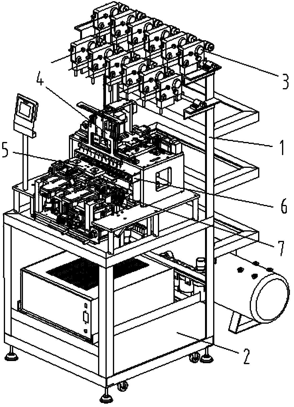
[0033] Such as Figure 1-Figure 8 As shown, the specific structure of the present invention is: an inductance automatic feeding and winding machine, which includes a frame 1 and a power distribution control box 2, the middle part of the frame 1 is provided with a loading rotating device 6, and the The upper part of the loading and rotating device 6 cooperates with the wire delivery device 3 through the wire insertion device 4, and the front part is equipped with a feeding docking device 5, and the described feeding docking device 5 cooperates with the feeding device 7 at the bottom of the frame 1, The ...


PUM


Abstract

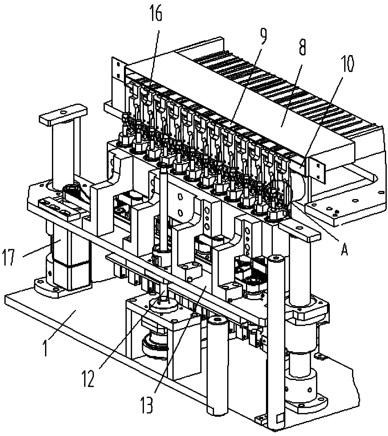
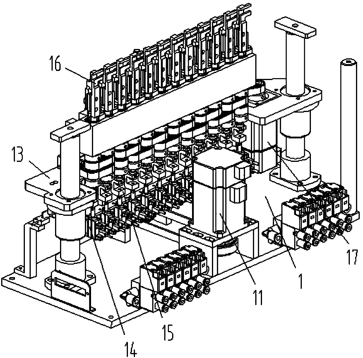
The invention relates to an automatic feed winding machine for inductance. The automatic feed winding machine comprises a rack and a distribution control box, a load rotating device is arranged in the middle of the rack, the upper portion of the load rotating device is matched with a wire plugging device and a wire conveying device, a feed docking device is fittingly arranged at the front portion of the load rotating device, the feed docking device is matched with a feeding device at the lower portion of the rack, the feed docking device comprises a docking seat arranged on the rack, a docking lifting cylinder is arranged on the docking seat and is connected with a docking lifting seat, a forward and backward receiving motion cylinder is arranged at the lower portion of the docking lifting seat and is connected with a receiving block made from electromagnet, receiving grooves matched with products are evenly formed in the receiving block, a forward and backward pushing motion cylinder is arranged at the upper portion of the docking lifting seat and is connected with a forward and backward pushing motion seat, and rotating pushing heads matched with the products are evenly arranged on the forward and backward pushing motion seat. By the arrangement, feeding efficiency is guaranteed, and meanwhile, quality in feeding and subsequent winding is guaranteed as well.

Description

technical field [0001] The invention relates to the field of winding equipment, in particular to an inductance automatic feeding and winding machine. Background technique [0002] Inductance is a commonly used electronic component. During its processing, its skeleton needs to be wound. Most of the existing windings need to be loaded and unloaded by hand, and positioning is required every time they are put up, which consumes a lot of manpower. , It is impossible to realize continuous and uninterrupted rotating winding, which will reduce the use efficiency of the equipment. At the same time, there will be differences in the amount of manual loading, which will cause corresponding errors and easily affect the consistency of the same inductance. Contents of the invention [0003] The purpose of the present invention is to provide an inductance automatic feeding and winding machine, through the magnetic material connecting block of the feeding docking device, the product clampe...

Claims


Application Information

Patent Timeline
Patent Type & Authority Patents(China)
IPC IPC(8): H01F41/066H01F41/096
CPCH01F41/064H01F41/082H01F41/096
Inventor 邓君徐红娇何楚亮
Owner TONGXIANG YAORUN ELECTRONICS
Learn More