
A bend-resistant flexible cable

A flexible cable, anti-bending technology, applied in the field of power cables, can solve the problems of rigidity and difficult handling of cables, and achieve the effect of avoiding excessive twisting and damage.

Active Publication Date: 2018-05-25
中山市科进电源线有限公司
View PDF7 Cites 0 Cited by
  • Summary
  • Abstract
  • Description
  • Claims
  • Application Information

AI Technical Summary

Problems solved by technology

This would have the disadvantage that the tube would become very rigid and all cables would be rigid and difficult to handle

Method used


Image

  • A bend-resistant flexible cable
  • A bend-resistant flexible cable

Examples


Embodiment Construction

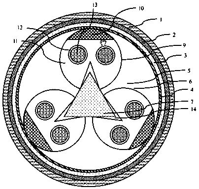
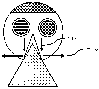
[0018] see figure 1 , the present invention provides a bending-resistant flexible cable, which includes an electric transmission unit 6, a cylindrical water-proof layer 4 that is sequentially coated on the outer surface of the electric transmission unit 6, an inner sheath 3, an armor layer 2, an outer In the sheath 1, there are 3-7 electrical transmission units 6, which are independent of each other and placed in the water-proof layer 4 together. Two power transmission conductors 13 covered with an insulating layer 12, the electric transmission unit 6 is cylindrical, and both are inscribed with the water-proof layer 4; and along the center line of the water-proof layer 4 (ie, the central axis of the cable) The extended section is an elastic core 7 with a regular N-sided shape, wherein N is 3-7, and the electric transmission unit 6 is respectively provided with fan-shaped grooves 14 along its center line to the elastic core 7, and the positive side of the elastic core 7 is The...


PUM


Abstract

The invention provides a bending-resistant flexible cable, which includes an electric transmission unit, a cylindrical water-proof layer coated in sequence on the outer surface of the electric transmission unit, an inner sheath, an armor layer, and an outer sheath. The number of transmission units is 3-7, which are independent of each other and placed in the water-resisting layer. Each electrical transmission unit includes two electrical transmission conductors respectively covered with insulating layers that are placed in a flexible sleeve. The electric transmission unit is cylindrical, and all are inscribed with the water-resistant layer; it is characterized in that: it also includes an elastic core with a regular N-sided cross-section extending along the center line of the water-resistant layer, wherein N is 3-7, so The electrical transmission units are respectively provided with fan-shaped slots along their centerlines to the elastic core, and the N vertices of the regular N-gon of the elastic core are respectively embedded in the fan-shaped slots, and the central angles of the fan-shaped slots are less than the top angle.

Description

technical field [0001] The invention relates to a cable, in particular to a bending-resistant flexible cable and a power cable used between communication equipment and user terminals. Background technique [0002] In the international application WO 97 / 40504A1 a self-supporting electrical cable is described which has a shielding band around an insulated electrical conductor which effectively protects the cable when it is suspended from a fixed point. The cables can be equipped with tubes in the above mentioned areas. International application WO 2004 / 006272 A1 describes a cable having a shielding strip of partially conductive material which is laid along the cable in the region between the insulated electrical conductor and the cable sheath. Conductive wires are laid in the strip along its entire length and form an effective shield to cut off the cable voltage if the cable is penetrated by a conductive object. Furthermore, tubes may also be arranged in such cables. [000...

Claims


Application Information

Patent Timeline
Patent Type & Authority Patents(China)
IPC IPC(8): H01B7/18H01B7/04H01B9/00
CPCH01B7/04H01B7/1815H01B7/184H01B7/1875H01B7/1895H01B9/00H01B9/005G02B6/443G02B6/4483G02B6/44384
Inventor 吴群
Owner 中山市科进电源线有限公司
Learn More