Aero-engine high pressure turbine disc optimization design system based on particle swarm and method

An aero-engine and high-pressure turbine technology, which is used in design optimization/simulation, calculation, special data processing applications, etc., and can solve the problems of large calculation granularity of grid crowding degree, inability to reflect the characteristics of file distribution, and easy loss of boundaries and non-inferior solutions. , to ensure uniformity and diversity, avoid random abandonment, and achieve the effect of accurate grid positioning

Active Publication Date: 2017-05-31
NORTHEASTERN UNIV
View PDF5 Cites 5 Cited by
  • Summary
  • Abstract
  • Description
  • Claims
  • Application Information

AI Technical Summary

Problems solved by technology

Thermal expansion and contraction as well as high-speed rotation lead to radial deformation of the high-pressure turbine disk, resulting in tip clearance management problems: too loose tip clearance increases gas leakage at the tip, and too tight tip clearance causes blade and machine friction between the casings, so many commercial aircraft engines use active thermal control technology to manage this gap
However, this simplification has the following defects: 1) The calculation granularity of the grid congestion degree is too large, which cannot reflect the distribution characteristics of the archives in each grid, and there is a large gap between the grid positioning results and the actual distribution of each particle in the archives
2) Randomly deleting non-inferior solutions in the second step may lead to uneven distribution of the frontier and easy loss of non-inferior solutions at the border

Method used


Image

  • Aero-engine high pressure turbine disc optimization design system based on particle swarm and method
  • Aero-engine high pressure turbine disc optimization design system based on particle swarm and method
  • Aero-engine high pressure turbine disc optimization design system based on particle swarm and method

Examples


Embodiment Construction

[0054] The specific implementation manners of the present invention will be further described in detail below in conjunction with the accompanying drawings and embodiments. The following examples are used to illustrate the present invention, but are not intended to limit the scope of the present invention.

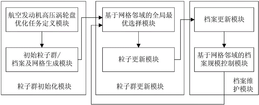
[0055] Such as figure 1 As shown, the present embodiment provides a particle swarm-based high-pressure turbine disk optimization design system for aero-engines, which includes a particle swarm initialization module, a particle swarm update module, and a file maintenance module for aero-engine high-pressure turbine disks. The final file obtained is Multi-objective optimization results.

[0056] The aero-engine high-pressure turbine disk particle swarm initialization module includes an aero-engine high-pressure turbine disk optimization task definition module and an initial particle swarm / file and grid generation module.

[0057] The aero-engine high-pressure turbine disk ...


PUM


Abstract

The invention provides an aero-engine high pressure turbine disc optimization design system based on particle swarm and method, and relates to a design technology field of the aero-engine. The system comprises a definition module of the optimization task of the aero-engine high pressure turbine disc, a primary particle swarm / file and a grid generation module, a global optimum selection module based on a gridding neighborhood, a particle update module, a file update module and a file size control module based on the gridding neighborhood, first the gridding jam index precision is improved by using active volume of file in gridding, then the particle jam distance is calculated in the finite region by using the gridding neighborhood message, the confidence level operand is provided for selecting the global optimum and deleting the file particle, the obtained ultimately file is the result of a plurality of the target optimization. During designing a plurality of the target optimization for the aero-engine high pressure turbine disc, starting from increasing precision of the global optimum in particle swarm optimization and of the non-particle deleting, the system and method provides the high-quality result of a plurality of the target optimization.

Description

technical field [0001] The invention relates to the technical field of aero-engine design, in particular to a particle swarm-based high-pressure turbine disc optimization design system and method for an aero-engine. Background technique [0002] The high-pressure turbine is the most important and expensive component of a modern aero-engine system. The high-pressure turbine disk is several times the mass of the low-pressure turbine disk, which affects the efficiency, stability, service life and performance of the engine. The weight reduction of the high-pressure turbine disk has always been the primary concern of designers. Thermal expansion and contraction as well as high-speed rotation lead to radial deformation of the high-pressure turbine disk, resulting in tip clearance management problems: too loose tip clearance increases gas leakage at the tip, and too tight tip clearance causes blade and machine friction between the casings, so many commercial aircraft engines use a...

Claims


Application Information

Patent Timeline
Patent Type & Authority Applications(China)
IPC IPC(8): G06F17/50
CPCG06F30/20G06F2111/10
Inventor 崔东亮冯国奇杜仲徐泉王良勇许美蓉
Owner NORTHEASTERN UNIV
Why Eureka
Try Eureka