
An optical reconnaissance device that can be dropped on the aircraft

A reconnaissance device and drop-in technology, which is applied to the field of drop-in optical reconnaissance devices, can solve the problems of limited environmental conditions and difficulty in rapidity of the optical reconnaissance system, and achieve the effect of improving the adaptability of environmental conditions and the efficiency of layout.

Active Publication Date: 2019-05-03
COMMANDING AUTOMATION TECHN RANDD & APPL CENT THE FOURTH ACADEMY CASIC
View PDF10 Cites 0 Cited by
  • Summary
  • Abstract
  • Description
  • Claims
  • Application Information

AI Technical Summary

Problems solved by technology

[0003] The purpose of the present invention is to provide a type of optical reconnaissance device that can be placed on the plane to solve the problem that the layout of the traditional optical reconnaissance system is limited by environmental conditions and it is difficult to use it quickly and on the plane

Method used


Image

  • An optical reconnaissance device that can be dropped on the aircraft
  • An optical reconnaissance device that can be dropped on the aircraft
  • An optical reconnaissance device that can be dropped on the aircraft

Examples


Embodiment Construction

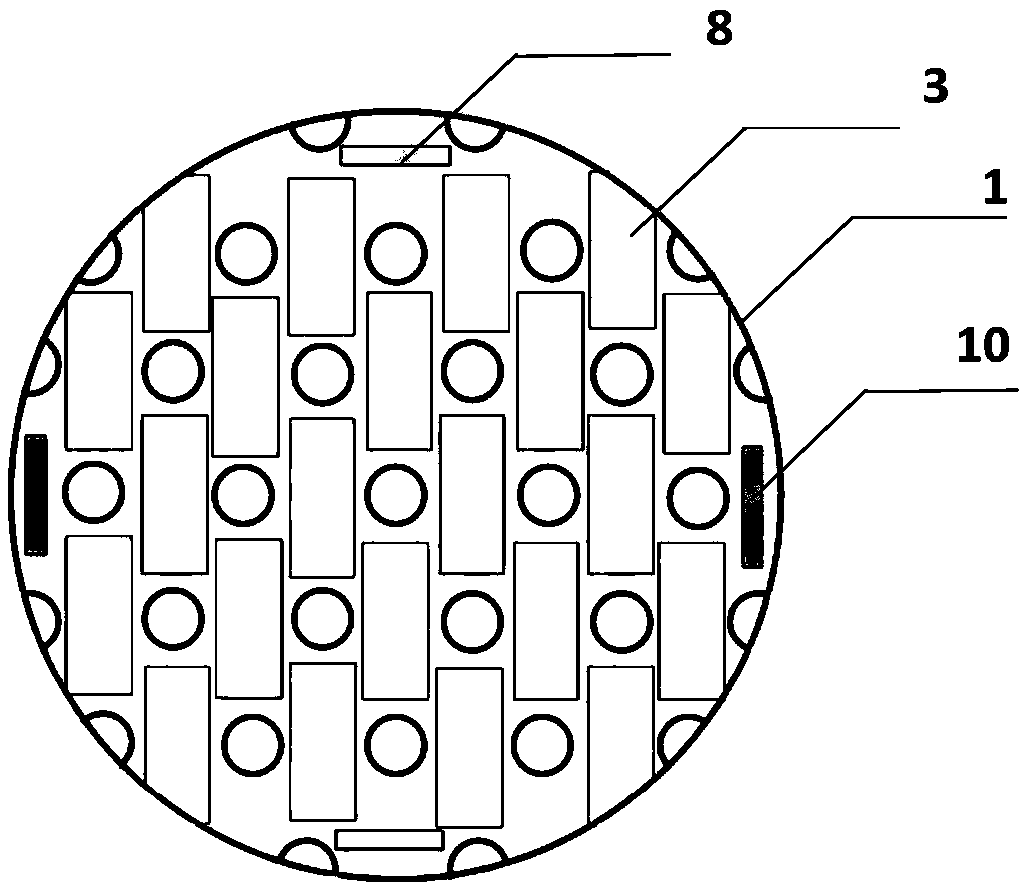
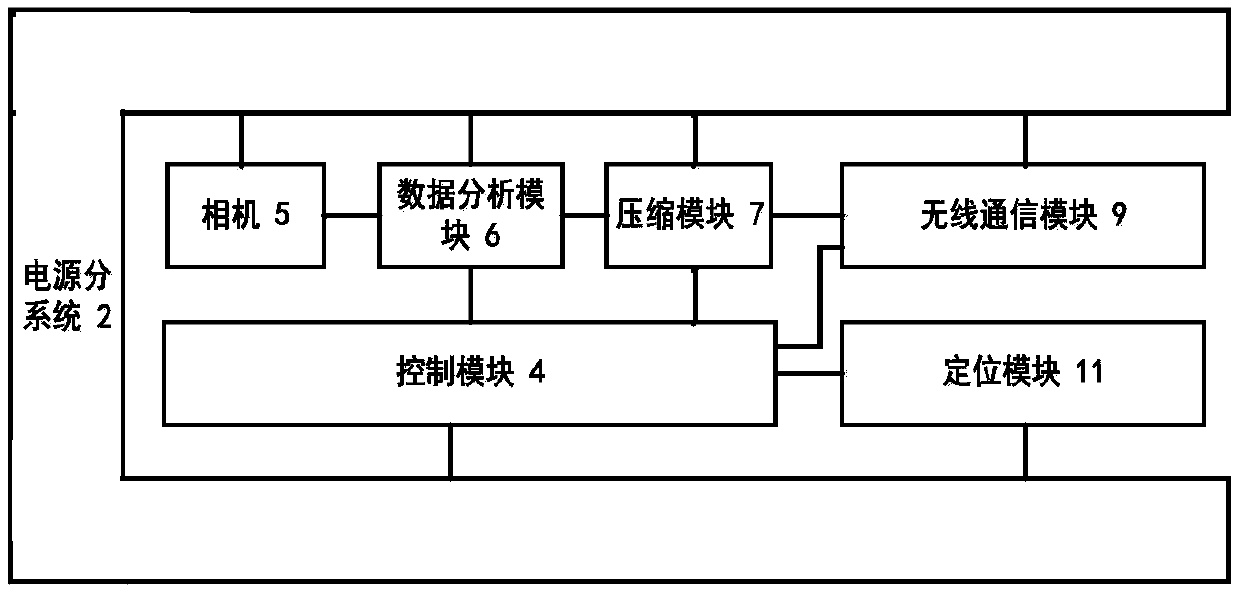
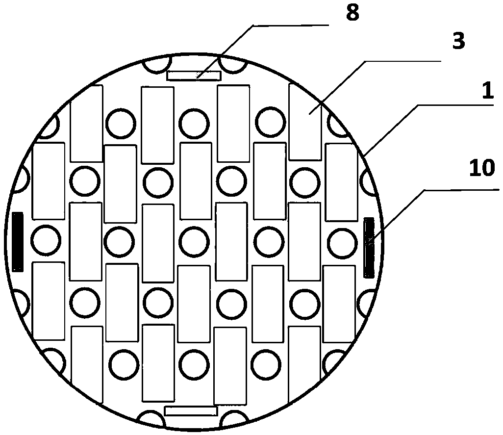
[0029] An optical reconnaissance device that can be placed on the plane, including: a spherical shell 1, a power supply subsystem 2, a solar film patch 3, a control module 4, a camera 5, a data analysis module 6, a compression module 7, a communication antenna 8, and a wireless communication module 9. Positioning the antenna 10 and the positioning module 11 .

[0030] The power supply subsystem 2 includes: a battery and a gate circuit.

[0031] The function of the control module 4 is: to control the internal working sequence of the improvised launchable optical reconnaissance device through a prefabricated control program.

[0032] The function of the data analysis module 6 is: to acquire the image collected by the camera, and use the target detection algorithm to perform target detection on the acquired image, and judge whether the image contains a target.

[0033] The function of the compression module 7 is to compress the image containing the target by using a compression ...


PUM


Abstract

The invention discloses an optical scouting apparatus deployable as occasion requires, comprising a spherical shell (1), a power subsystem, a solar film patch (3), a control module, a camera, a data analysis module, a compression module, a communication antenna (8), a wireless communication module, a positioning antenna (10), and a positioning module; the optical scouting apparatus deployable as occasion requires can acquire omnidirectional image information and detect a target in the acquired image information; once the target is discovered, an image including the target is uploaded; the apparatus can also upload its positional information at equal intervals, can stand by and restart according to commands, and may also use solar energy to charge its battery. The apparatus has no need for considering system installation angle and can be cast and remotely without recording a landing point, system adaptability to environmental conditions and system deployment efficiency are improved largely, and long-term stable monitoring for the periphery of a deploying point is achieved.

Description

technical field [0001] The invention relates to an optical reconnaissance device, in particular to an optical reconnaissance device that can be dropped on the spot. Background technique [0002] The optical reconnaissance system is an important means of obtaining information, and it is indispensable in applications such as border defense, important activity monitoring, and anti-terrorism. However, due to the limited field of view of the traditional optical reconnaissance system, it is necessary to adjust the orientation and attitude of the optical reconnaissance system during installation and layout to ensure that the optical reconnaissance system can obtain the information of the target area; in addition, in order to support the work of the optical reconnaissance system, it is necessary Connect the optical reconnaissance system with the power supply line to supply power to the system. It is necessary to connect the optical reconnaissance system with the communication line t...

Claims


Application Information

Patent Timeline
Patent Type & Authority Patents(China)
IPC IPC(8): G01V8/10H04N7/18
CPCG01V8/10H04N7/18
Inventor 曹扬吴京辉金彬邵光征刘娜杨柳
Owner COMMANDING AUTOMATION TECHN RANDD & APPL CENT THE FOURTH ACADEMY CASIC
Learn More