


Quick Research
Generate reliable direction feasibility study reports for your R&D in just a few steps.

Technical Q&A
Discover and master advanced knowledge NOW. Basics, ideas, possibilities, all at once.

Find Solutions
As an expert in R&D theories, this can generate solutions to your technical problems instantly.

Evaluate Feasibility
Analyze your overall solution with one click, know your potential R&D risks in advance.

Monitor Landscape
Get weekly tech updates, stay abreast of the latest tech innovations and key insights.
Automatic fault diagnosis device for power electronic circuit
A power electronic circuit and automatic diagnosis technology, which is applied in the direction of electronic circuit testing, measuring devices, measuring device casings, etc., can solve problems such as unsuitable circuits, bumps, clips accidentally falling off, etc., to reduce production costs and facilitate use.
- Summary
- Abstract
- Description
- Claims
- Application Information
AI Technical Summary
Problems solved by technology
Method used
Image

Examples
Embodiment 1
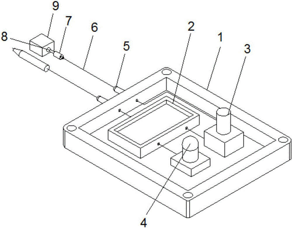
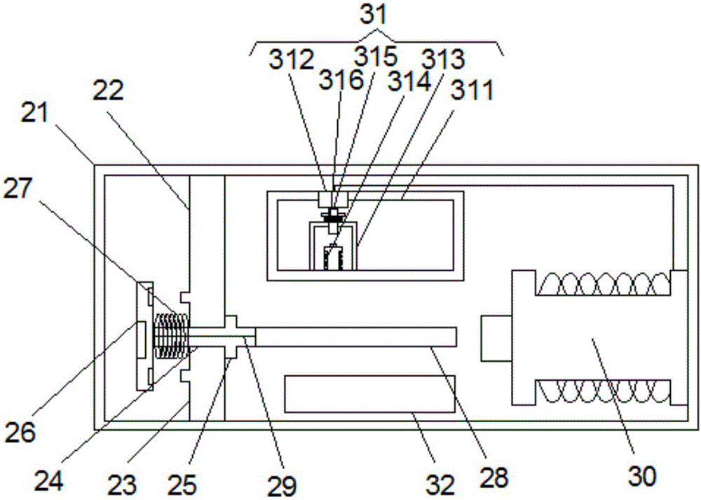
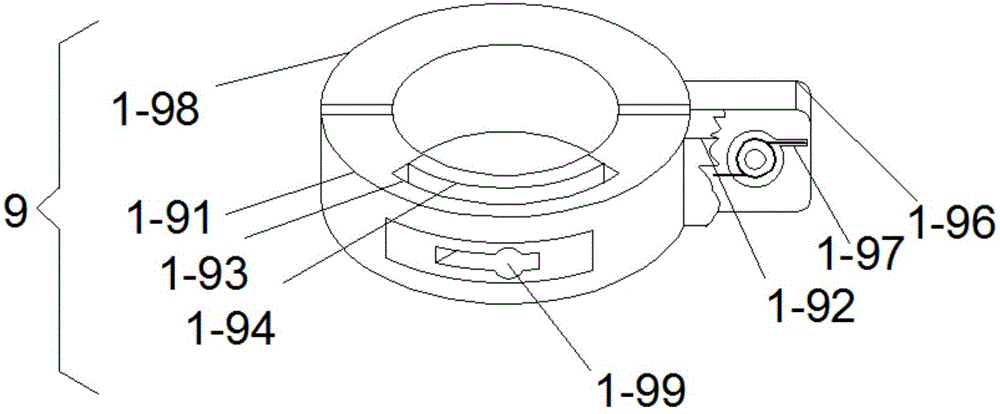
[0023] see figure 1 , figure 2 , image 3 , Figure 4 and Figure 8 , the present invention provides the first technical solution: a power electronic circuit fault automatic diagnosis device, comprising a housing 1, the left side of the bottom surface of the inner cavity of the housing 1 is fixedly connected with a control device 2, the housing 1 The upper right corner of the bottom surface of the inner cavity is fixedly connected with a two-way switch 3, the lower right corner of the bottom surface of the inner cavity of the housing 1 is fixedly connected with an indicator light 4, and the left side of the housing 1 is fixed with a clamping post 5, and the clamping The inner side of the wire column 5 is sleeved with a spiral wire 6, and the left side of the spiral wire 6 is fixed with a clamping rod 7, and the left side of the clamping rod 7 is integrally formed with a spherical clamping block 8, and the spherical clamping The left side of the block 8 is clamped with a c...
Embodiment 2
[0031] see figure 1 , figure 2 , Figure 5 , Figure 6 and Figure 8 , the present invention provides a second technical solution: a power electronic circuit fault automatic diagnosis device, comprising a housing 1, a control device 2 is fixedly connected to the left side of the bottom surface of the inner cavity of the housing 1, and the housing 1 The upper right corner of the bottom surface of the inner cavity is fixedly connected with a two-way switch 3, the lower right corner of the bottom surface of the inner cavity of the housing 1 is fixedly connected with an indicator light 4, and the left side of the housing 1 is fixed with a clamping post 5, and the clamping The inner side of the wire column 5 is sleeved with a spiral wire 6, and the left side of the spiral wire 6 is fixed with a clamping rod 7, and the left side of the clamping rod 7 is integrally formed with a spherical clamping block 8, and the spherical clamping The left side of the block 8 is clamped with a...
Embodiment 3
[0039] see figure 1 , figure 2 , Figure 7 and Figure 8 , the present invention provides a third technical solution: a power electronic circuit fault automatic diagnosis device, including a housing 1, the left side of the bottom surface of the inner cavity of the housing 1 is fixedly connected with a control device 2, the housing 1 The upper right corner of the bottom surface of the inner cavity is fixedly connected with a two-way switch 3, the lower right corner of the bottom surface of the inner cavity of the housing 1 is fixedly connected with an indicator light 4, and the left side of the housing 1 is fixed with a clamping post 5, and the clamping The inner side of the wire column 5 is sleeved with a spiral wire 6, and the left side of the spiral wire 6 is fixed with a clamping rod 7, and the left side of the clamping rod 7 is integrally formed with a spherical clamping block 8, and the spherical clamping The left side of the block 8 is clamped with a chuck 9, and the...
PUM
 Abstract
Description
Claims
Application Information
 - R&D Engineer
- R&D Manager
- IP Professional
- Industry Leading Data Capabilities
- Powerful AI technology
- Patent DNA Extraction
Browse by: Latest US Patents, China's latest patents, Technical Efficacy Thesaurus, Application Domain, Technology Topic, Popular Technical Reports.
© 2024 PatSnap. All rights reserved.Legal|Privacy policy|Modern Slavery Act Transparency Statement|Sitemap|About US| Contact US: help@patsnap.com