A system for measuring quantum efficiency within an image sensor pixel

An image sensor and internal quantum efficiency technology, applied in the field of aerospace, to achieve the effect of wide application and convenient adjustment

Active Publication Date: 2019-05-17
NAT SPACE SCI CENT CAS
View PDF6 Cites 0 Cited by
  • Summary
  • Abstract
  • Description
  • Claims
  • Application Information

AI Technical Summary

Problems solved by technology

[0004] The purpose of the present invention is to overcome the defects of the system and method for measuring the quantum efficiency in the pixel of the image sensor by using the spot scanning method in the prior art, thereby providing a convenient measurement system for the quantum efficiency in the pixel of the image sensor

Method used


Image

  • A system for measuring quantum efficiency within an image sensor pixel
  • A system for measuring quantum efficiency within an image sensor pixel

Examples


Embodiment Construction

[0025] The system and method of the present invention will be further described in conjunction with the accompanying drawings.

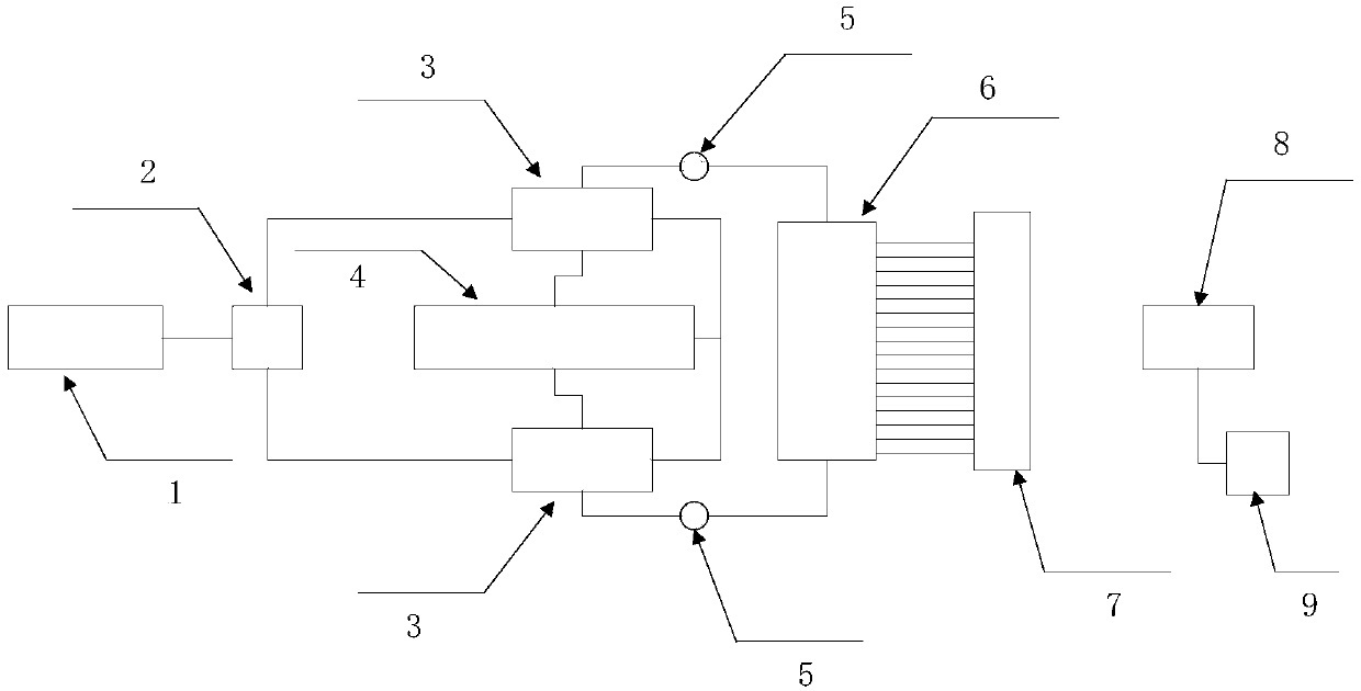
[0026] refer to figure 1 , the image sensor pixel quantum efficiency measurement system of the present invention includes: laser 1, optical fiber beam splitter 2, acousto-optic modulator 3, radio frequency synthesis and driver 4, polarization controller 5, optical switch 6, interference baseline 7, image sensor 8 and computing module 9. Wherein, the laser 1 provides laser light with stable wavelength and stable intensity; the optical fiber beam splitter 2 divides the laser output from the laser 1 into two laser beams with an intensity of 1:1; the two laser beams with an intensity of 1:1 are respectively input to two In an acousto-optic modulator 3, the acousto-optic modulator 3 forms a difference frequency for the two beams of laser light under the control of the radio frequency synthesis and driver 4 and locks it, and the polarization controller 5 ...


PUM

PropertyMeasurementUnit
wavelengthaaaaaaaaaa

Abstract

The invention relates to a system for measuring the pixel internal quantum efficiency of an image sensor. The system comprises a laser device, an optical fiber splitting device, acoustic optical modulators, a radio frequency synthesis and driving device, a polarization controller, an optical switch, an interference base line, an image sensor and a computation module, wherein the laser device provides laser with stable wavelength and intensity; the optical fiber splitting device splits laser, output by the laser device, into two bundles of laser with the intensity ratio of 1:1, which are input into the two acoustic optical modulators, the acoustic optical modulators form and lock difference frequency for the two laser bundles under the control of the radio frequency synthesis and driving device, and the polarization controller is used for adjusting the polarization direction of the two laser bundles with difference frequency to form four-step phase shift interference strips; the optical switch is used for switching light in optical fiber to different interference base lines; the interference base lines are used for evenly covering frequency space; the an image sensor is used for acquiring four-step phase shift images; and the computation module is used for real domain distribution of pixel internal quantum efficiency through the four-step phase shift images.

Description

technical field [0001] The invention relates to the field of aerospace, in particular to a system for measuring quantum efficiency in an image sensor pixel. Background technique [0002] Solid-state image sensors (CCD, CMOS-APS, etc.) have occupied a dominant position in the field of optical imaging. Such image sensors have a wide range of applications in many professional fields. With the gradual improvement of the performance of solid-state image sensors in terms of readout noise, charge transfer efficiency, readout time, quantum efficiency, and low power consumption, solid-state image sensors have almost become a unique choice in many applications. In the practical application of image sensors, many methods and technologies for calibrating the quantum efficiency (flat-field response) between pixels of image sensors have been developed. These methods and technologies all assume that the quantum efficiency is consistent and uniform inside the pixel. However, in reality, t...

Claims


Application Information

Patent Timeline
Patent Type & Authority Patents(China)
IPC IPC(8): G01N21/39
CPCG01N21/39
Inventor 李海涛李保权桑鹏曹阳
Owner NAT SPACE SCI CENT CAS
Why Eureka
Try Eureka