
Digital rate integrating gyroscope control method based on parametric excitation and platform

A technology of parameter excitation and control method, which is applied in the direction of speed measurement by gyro effect, gyroscope/steering sensing equipment, measuring device, etc., and can solve problems such as error, rate integration mode failure, drive component error circuit, etc.

Active Publication Date: 2017-05-31
TSINGHUA UNIV
View PDF4 Cites 0 Cited by
  • Summary
  • Abstract
  • Description
  • Claims
  • Application Information

AI Technical Summary

Problems solved by technology

However, due to the uncertainty of material properties and processing, gyroscopes have non-ideal properties such as anisotropic elasticity and anisotropic damping.
In a rate-integrating gyro, the harmonic oscillator vibrates freely, making the measurement accuracy susceptible to gyro non-idealities and presenting control challenges
Among them, anisotropic elasticity and anisotropic damping are the two main error sources of the rate-integrating gyroscope, and anisotropic elasticity and anisotropic damping will cause a quadrature vibration with a phase orthogonal to the main vibration of the gyroscope, resulting in an angular output error, And if the anisotropic elasticity and anisotropic damping are too large, the rate integral mode will also fail
In addition, the error of the motion detection part of the gyro structure, the error of the drive part and the error of the circuit gain will further cause the output error of the rate integrating gyro

Method used


Image

  • Digital rate integrating gyroscope control method based on parametric excitation and platform
  • Digital rate integrating gyroscope control method based on parametric excitation and platform
  • Digital rate integrating gyroscope control method based on parametric excitation and platform

Examples


Embodiment Construction

[0064] The present invention will be described in detail below in conjunction with the accompanying drawings and embodiments.

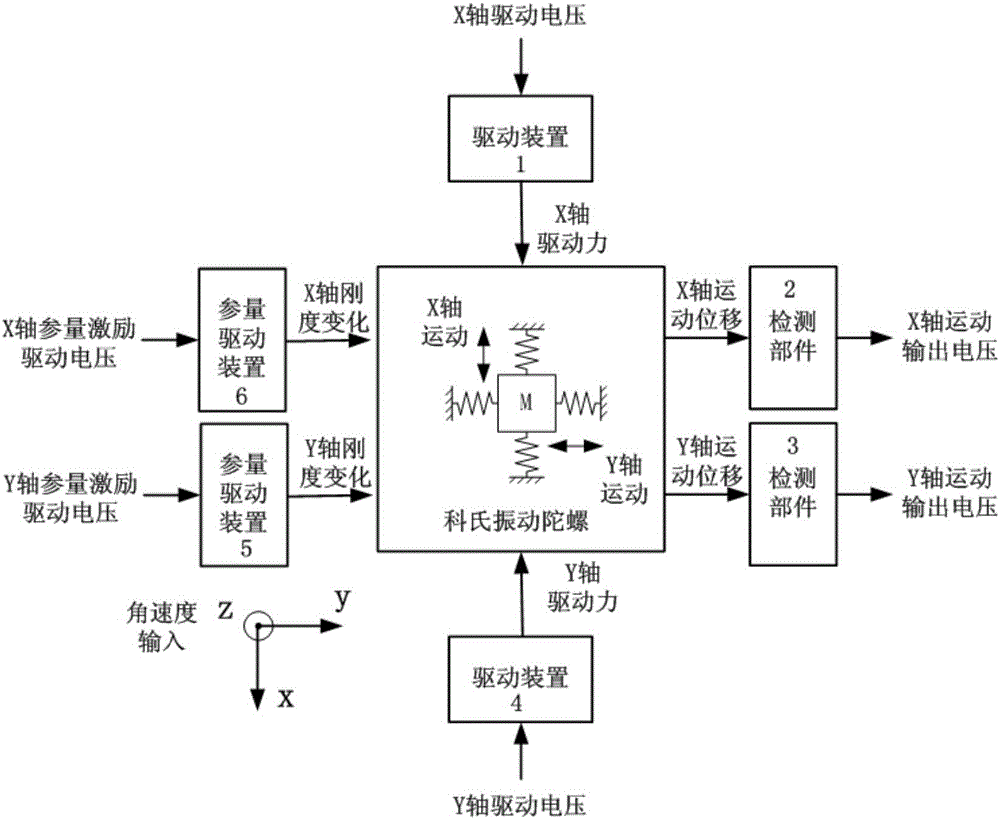
[0065] Such as figure 1 As shown, the control method and platform of the present invention are applicable to the biaxially symmetrical Coriolis vibrating gyro structure, and of course can also be applied to other Coriolis vibrating gyro structures. The biaxially symmetrical Coriolis vibrating gyroscope has two moving directions of the X axis and the Y axis, and the detection parts, the driving device and the parameter driving device are respectively arranged in the X axis and the Y axis moving directions; the detection parts are used to detect the X axis respectively. and Y-axis motion displacement and converted into X-axis and Y-axis motion output voltage, respectively applying a driving voltage to the drive device in the X-axis and / or Y-axis motion direction will apply a motion along the X-axis and / or Y-axis to the vibrating gyroscope The driving f...


PUM


Abstract

The invention relates to a digital rate integrating gyroscope control method based on parametric excitation and a platform. The method comprises the steps that 1, rate integrating gyroscope syntropy reference quantity, an orthogonal reference quantity initial value, and a rate integrating gyroscope vibration energy preset value are set; 2, rate integrating gyroscope X and Y axis motion output voltage digital quantities are collected and detection component error correction is performed; 3, the corrected X and Y axis motion output voltage digital quantities are subjected to 0 and 90-degree phase-sensitive demodulation; 4, intermediate variables are calculated; 5, phase-sensitive demodulation reference signals, parametric excitation drive voltage phase reference signals and drive voltage phase reference signals are calculated; 6, X and Y axis parametric excitation drive voltage digital quantities are calculated; 7, a sine value and a cosine value of the gyroscope vibration angle are calculated; 8, X and Y axis drive voltage digital quantities are calculated; 9, the phase-sensitive demodulation reference signals are subjected to 0 and 90-degree phase conversion to be adopted as the syntropy reference quantity and the orthogonal reference quantity of a next sampling moment, and the step 2 is executed.

Description

technical field [0001] The invention belongs to the technical field of sensor detection and control, and in particular relates to a parameter excitation-based digital rate-integrating gyroscope control method and platform with an error correction function. Background technique [0002] Due to its small size, low power consumption, and low cost, the Coriolis vibrating gyroscope has become a very popular technical field and has been widely used. At present, there are two main development trends of Coriolis vibrating gyroscopes, one is a mass-market low-cost type for the mass consumer market, and the other is a high-precision type for the military field. For the second requirement of the development of the Coriolis vibrating gyroscope, it is necessary to explore methods to improve the accuracy of the Coriolis vibrating gyroscope. [0003] Coriolis vibrating gyroscopes can be divided into rate gyroscopes and rate-integrating gyroscopes according to the output physical quantity....

Claims


Application Information

Patent Timeline
Patent Type & Authority Applications(China)
IPC IPC(8): G01C19/5776
Inventor 周斌张嵘宋明亮侯波
Owner TSINGHUA UNIV
Learn More