A Calibration Method for Probe Center of Large Gear Machine Tool Based on Segment Gear Measuring Tool

A technology of sector gears and large gears, which is applied to measuring devices and instruments, can solve the problems of low probe calibration accuracy, linear amplification of calibration errors, and reduced calibration efficiency, so as to reduce calibration costs, facilitate operation, and improve calibration accuracy. Effect

Active Publication Date: 2019-04-02
江苏恒源精密机械制造有限公司
View PDF5 Cites 0 Cited by
  • Summary
  • Abstract
  • Description
  • Claims
  • Application Information

AI Technical Summary

Problems solved by technology

There are two main reasons. One is that the calibration method of the traditional large-scale gear machine tool has the problem of low calibration accuracy. The traditional large-scale gear machine tool usually uses cylindrical calibration or standard ball calibration. This calibration method is due to the large rotating diameter of the workpiece. The calibration error is linearly enlarged, and the calibration accuracy of the probe is not high; second, the standard gear calibration method used on small gear machine tools is not feasible on large gear machine tools, because large machine tools are limited by the travel of the front end of the probe, and can only be used with larger dimensions. Large standard gear, but this will increase the cost of the measuring tool, and the calibration efficiency will be greatly reduced due to inconvenient clamping

Method used


Image

  • A Calibration Method for Probe Center of Large Gear Machine Tool Based on Segment Gear Measuring Tool
  • A Calibration Method for Probe Center of Large Gear Machine Tool Based on Segment Gear Measuring Tool
  • A Calibration Method for Probe Center of Large Gear Machine Tool Based on Segment Gear Measuring Tool

Examples


Embodiment Construction

[0042] The present invention will be further described below in conjunction with the accompanying drawings and specific embodiments, but the protection scope of the present invention is not limited thereto.

[0043] A method for calibrating the probe center of a large gear machine tool based on a sector gear measuring tool is characterized in that it includes the following steps:

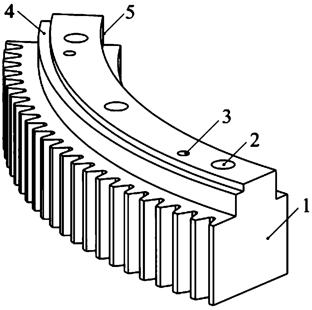
[0044] S01: Make sector gear measuring tool 1;

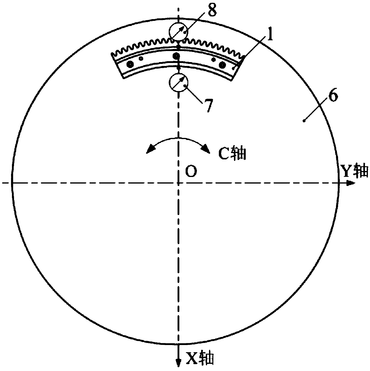
[0045]S02: Calibrate the plane of the sector gear measuring tool 1 parallel to the working plane of the rotary workpiece table 6 of the machine tool, and calibrate the sector gear measuring tool 1 and the rotation axis of the rotary workpiece table 6 to be coaxial;

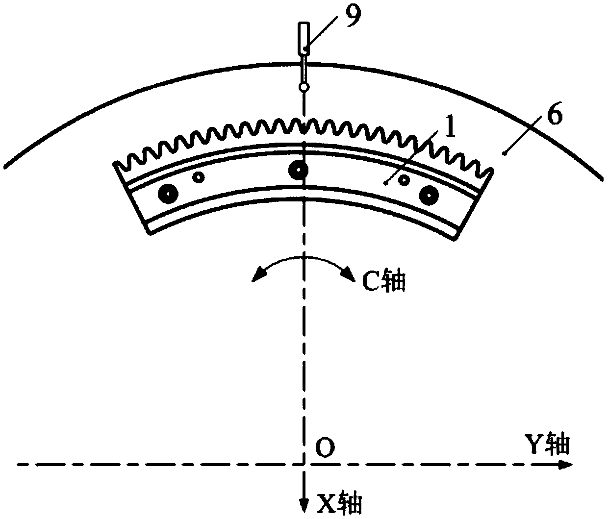
[0046] S03: measuring sampling points, specifically, selecting a number of tooth grooves on the sector gear measuring tool 1, executing the tooth profile measurement program, and measuring the selected points of the tooth grooves to obtain tooth surface measurement data of the tooth groov...


PUM


Abstract

The invention provides a method for calibrating the center of the measuring head of a large gear machine tool based on a sector gear gauge, comprising the following steps: S01, making a sector gear gauge; S02, making the plane of the sector gear gauge parallel to the working plane of a rotary work piece table of the machine tool through correction, and making the sector gear gauge coaxial with the axis of rotation of the rotary work piece table through correction; S03, performing measurement sampling: selecting a plurality of tooth slots from the sector gear gauge, performing a tooth profile measurement program, and carrying out measurement sampling on the selected tooth slots to get the tooth surface measurement data of the tooth slots; and S04, according to the acquired tooth surface data of the tooth slots, analyzing the slope direction and size of tooth-direction slope deviation of the tooth profile, calculating the amount of position error correction of the center of the measuring head, and calibrating the center position of the measuring head. By using a general sector gear gauge, the cost of machining equipment of large numerical control gears is reduced. The method has the advantages of simple adjustment and easy operation, and can improve the measuring head calibration accuracy and calibration efficiency of large gear machine tools.

Description

technical field [0001] The invention relates to a method for calibrating the accuracy of a machine tool measuring head, in particular to a method for calibrating the center of a large gear machine tool measuring head based on a sector gear measuring tool. Background technique [0002] Large gears are used as key components for large wind power generation, forging equipment, metallurgical equipment and ship installations. Due to the large volume and mass of large gear workpieces, and inconvenient clamping, it is not convenient to measure on a three-coordinate measuring instrument or a gear measuring instrument. However, there is a secondary clamping error in the off-position measurement method, which will reduce the gear measurement accuracy. In recent years, large-scale gear grinding, hobbing, and gear shaping machine tools produced by large-scale gear machine tool manufacturing companies at home and abroad are equipped with on-site measurement systems. This on-site measurem...

Claims


Application Information

Patent Timeline
Patent Type & Authority Patents(China)
IPC IPC(8): G01B21/00
CPCG01B21/00
Inventor 郭二廓任乃飞
Owner 江苏恒源精密机械制造有限公司
Why Eureka
Try Eureka