Portable high-precision inner round hole contour error automatic measuring device
A contour error, automatic measurement technology, applied in electromagnetic measurement devices, electric/magnetic contour/curvature measurement, etc., can solve the problem that cannot meet the requirements of high precision and automatic measurement of machinery manufacturing enterprises, and the details of round hole contour cannot be measured and inspected. The problems such as the overall error of the round hole cannot be obtained, and the effect of improving the stability and accuracy of the measurement, convenient carrying and operation, and low noise can be achieved.
- Summary
- Abstract
- Description
- Claims
- Application Information
AI Technical Summary
Problems solved by technology
Method used
Image
Examples
Embodiment 1
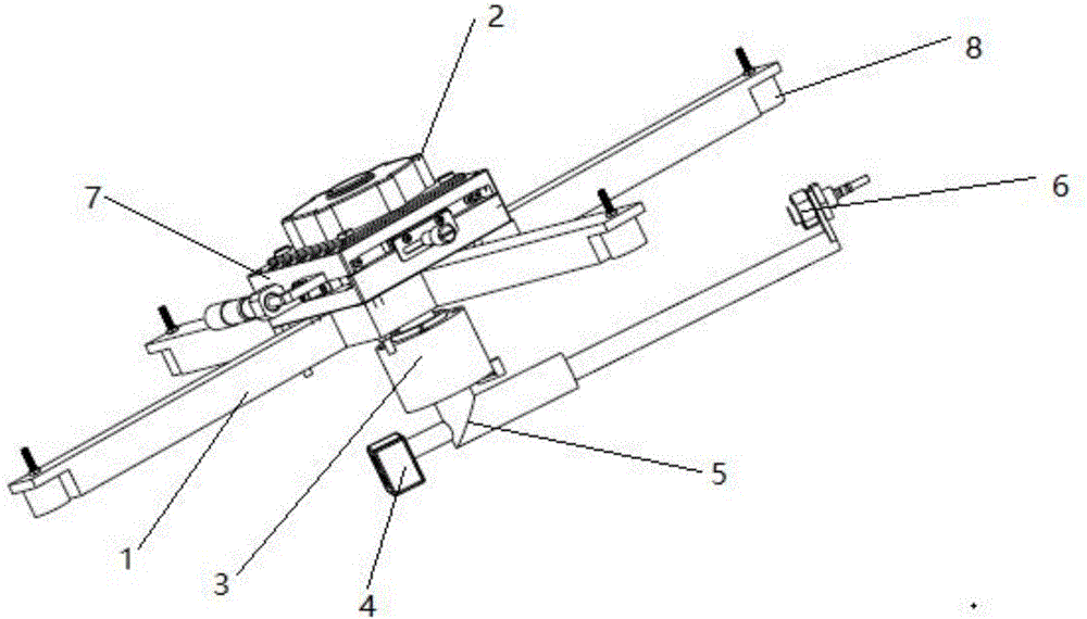
[0027] see figure 1 , the present invention provides a portable high-precision automatic measurement device for the contour error of inner circular holes, comprising a support frame 1 fixed on the end face of the hole to be measured, and the support frame 1 is provided with a scale for realizing the initial centering of the automatic measurement device; The support frame 1 is provided with an electromagnetic sucker 8 which is used to absorb to the end face of the hole to be measured and plays the role of fixing the support frame 1; the XY axis displacement platform 7 is fixed on the support frame 1, and the XY axis displacement platform 7 is fixed on the support frame 1. An ultrasonic motor 2 is fixed, and the rotating shaft of the ultrasonic motor 2 passes through the central hole of the XY axis displacement platform 7 and is fixedly connected with the upper end of the vertical bar of the inverted T-shaped measuring rod 5; one end of the horizontal rod of the measuring rod 5 ...
Embodiment 2
[0029] On the basis of Embodiment 1, the counterweight device 4 is a counterweight block, and the surface of the counterweight block is provided with threaded holes for increasing or decreasing the weight of the counterweight device 4 by mounting and dismounting screws.
[0030] The support frame 1 is a four-claw support, and each claw end of the support frame 1 is provided with a step of the same height as the electromagnetic chuck 8, and the electromagnetic chuck 8 is set in the step by a threaded mode; The center of the four-claw support is provided with a through hole; the rotation axis of the ultrasonic motor 2 passes through the center hole of the XY axis displacement platform 7 and the through hole at the center of the four-claw support and is connected to the vertical axis of the inverted T-shaped measuring rod 5. The upper end of the straight rod is fixedly connected.
[0031] The electromagnetic chuck 8 is electrically connected with the industrial computer, and the ...
PUM
 Abstract
Description
Claims
Application Information
 - R&D Engineer
- R&D Manager
- IP Professional
- Industry Leading Data Capabilities
- Powerful AI technology
- Patent DNA Extraction
Browse by: Latest US Patents, China's latest patents, Technical Efficacy Thesaurus, Application Domain, Technology Topic, Popular Technical Reports.
© 2024 PatSnap. All rights reserved.Legal|Privacy policy|Modern Slavery Act Transparency Statement|Sitemap|About US| Contact US: help@patsnap.com


