Stage lamp box equipment

A light box and equipment technology, applied in the direction of mechanical equipment, lighting and heating equipment, lighting auxiliary devices, etc., can solve the problems of difficult installation and disassembly, poor connection stability, cumbersome and laborious adjustment process, etc., to achieve convenient operation, free from installation and disassembly, The effect of simple structure

Inactive Publication Date: 2017-05-31
南京众慧网络科技有限公司
View PDF5 Cites 0 Cited by
  • Summary
  • Abstract
  • Description
  • Claims
  • Application Information

AI Technical Summary

Problems solved by technology

[0002] In order to achieve better visual effects on some large stages, lighting equipment is often used. However, this lighting equipment needs to change its orientation and angle frequently to meet the illumination requirements of different directions. The lighting equipment in the prior art is generally connected through activities. On the support rod, when it is necessary to adjust the direction and angle of the irradiation, it is done manually. The fixing method is not reliable, the connection stability is poor, the adjustment process is cumbersome and laborious, and the installation and disassembly are difficult, etc., which have great disadvantages. , it is difficult to meet the existing needs

Method used


Image

  • Stage lamp box equipment
  • Stage lamp box equipment
  • Stage lamp box equipment

Examples


Embodiment Construction

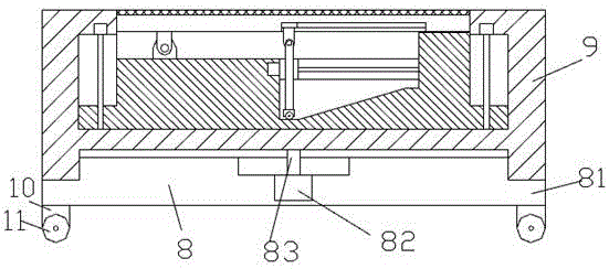
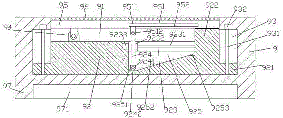
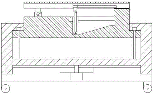
[0021] Such as Figure 1-Figure 5 As shown, a stage light box device of the present invention includes a base body 8 and a light box 9 arranged on the upper end of the base body 8 , the outer side of the base body 8 is fixed with a lower ring portion 81 , and the inside of the base body 8 is A third motor 82 is provided at the end, and the top of the third motor 82 is connected with a turning pin shaft 83 extending upwards. The top of the turning pin shaft 83 is fixedly connected with the middle end of the bottom of the light box 9. The light box 9. An upper ring portion 97 is fixed along the edge of the bottom, and an arc groove 971 is arranged inside the upper ring portion 97. The top of the seat body 8 enters the arc groove 971 and is connected in a rotational fit. The upper ring portion The bottom end surface of 97 abuts against the top surface of the lower ring portion 81 and is connected in operation. A cavity 91 is provided on the top of the light box 9, and a sliding p...


PUM


Abstract

The invention discloses stage lamp box equipment. The stage lamp box equipment comprises a seat and a lamp box arranged at the upper end of the seat. A lower ring part is fixedly arranged on the outer side of the seat. A third motor is arranged at the middle end in the seat. The top of the third motor is in operation connection with a rotary hinge pin extending upwards. The top end of the rotary hinge pin is fixedly connected with the middle end of the bottom of the lamp box. An upper ring part is fixedly arranged at the bottom edge of the lamp box and is internally provided with a circular arc groove. The top of the seat enters the circular arc groove and is in rotary fit connection with the circular arc groove. The bottom end face of the upper ring part abuts against the top end face of the lower ring part and is in rotary fit connection with the lower ring part. A cavity is arranged at the top in the lamp box and is internally provided with a sliding table. The stage lamp box equipment is simple in structure, convenient to operate and controlled in the cavity when not used and automatically extend out of the cavity when used. Cumbersome steps such as installation and disassembly can be avoided, and the light needs of different directions and angles can be met at the same time.

Description

technical field [0001] The invention relates to the technical field of stage lighting equipment, in particular to a stage light box equipment. Background technique [0002] In order to achieve better visual effects on some large stages, lighting equipment is often used. However, this lighting equipment needs to change its orientation and angle frequently to meet the illumination requirements of different directions. The lighting equipment in the prior art is generally connected through activities. On the support rod, when it is necessary to adjust the direction and angle of the irradiation, it is done manually. The fixing method is not reliable, the connection stability is poor, the adjustment process is cumbersome and laborious, and the installation and disassembly are difficult, etc., which have great disadvantages. , it is difficult to meet the existing needs. Contents of the invention [0003] The technical problem to be solved by the present invention is to provide a...

Claims


Application Information

Patent Timeline
Patent Type & Authority Applications(China)
IPC IPC(8): F21S8/00F21V17/12F21V21/14F21V21/06F21W131/105F21W131/406
CPCF21S8/00F21V17/12F21V21/06F21V21/14F21W2131/105F21W2131/406
Inventor 毛晨杰
Owner 南京众慧网络科技有限公司
Why Eureka
Try Eureka