Coaxial type shifting fork structure
A coaxial type and shifting fork shaft technology, applied in the field of coaxial shifting fork structure, can solve the problems of low smoothness and complex structure, and achieve the effects of high smoothness, simplified structure and low manufacturing cost
- Summary
- Abstract
- Description
- Claims
- Application Information
AI Technical Summary
Problems solved by technology
Method used
Image

Examples
Embodiment 1
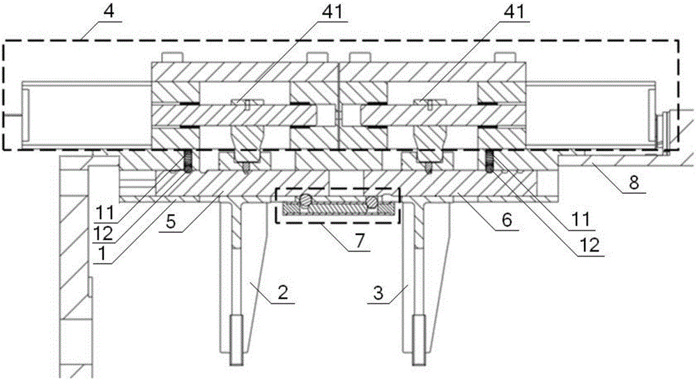
[0045] see Figure 1 to Figure 4 , a coaxial shift fork structure, including a mechanism base 1, a No. 1 shift fork 2, a No. 2 shift fork 3, a shift actuator 4, and the No. 1 shift fork 2 and No. The shaft is installed on the mechanism base 1, the shift actuator 4 includes a shift head 41, the shift fork shaft includes the first shift fork shaft 5 and the second shift fork shaft 6, the first shift fork shaft 5, the second shift fork shaft The No. 1 shift fork shaft 6 is coaxially installed in the mechanism base 1, and the No. 1 shift fork 2 and No. 2 shift fork 3 are installed on the No. 1 shift fork shaft 5 and No. 2 shift fork shaft 6 respectively. The shift head 41 The number is two, and the two shift heads 41 are respectively matched with the No. 1 shift fork 2 and the No. 2 shift fork 3; the structure of the No. 1 shift fork 2 and the No. 2. The No. 1 countersunk head lock nail 21 is fixedly connected to the No. 1 shift fork shaft 5, and the No. 2 shift fork 3 is fixedly...
Embodiment 2
[0047] Basic content is the same as embodiment 1, the difference is:
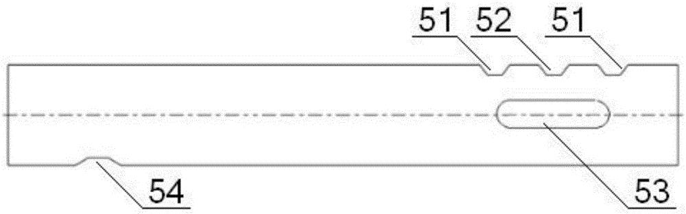
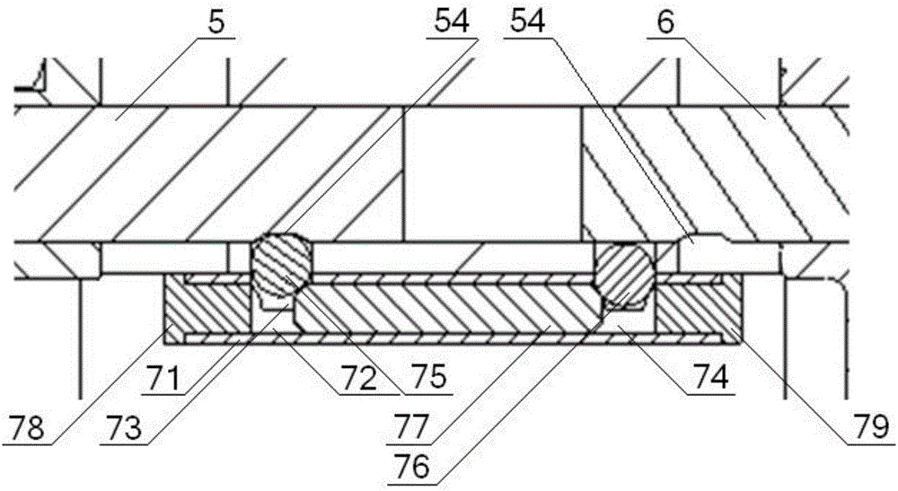
[0048] see Figure 1 to Figure 4 , the No. 1 shift fork shaft 5 has the same structure as the No. 2 shift fork shaft 6, and one side of the No. 1 shift fork shaft 5 and No. 2 shift fork shaft 6 is provided with a self-locking groove, and the No. 1 shift fork shaft 5. The other side of the No. 2 shift fork shaft 6 is provided with a No. 1 interlocking groove 54. The self-locking groove includes a working gear groove 51 and a neutral gear groove 52. The number of the working gear grooves 51 is two , the two working gear slots 51 are respectively located on both sides of the neutral gear slot 52; the No. 1 shift fork shaft 5 and the No. 2 shift fork shaft 6 are equipped with flat keys 53, and the mechanism base 1 is provided with a flat key for installation. The keyway of the key 53; the coaxial shift fork structure also includes an interlocking device 7, the interlocking device 7 is installed on the mechanis...
Embodiment 3
[0050] Basic content is the same as embodiment 1, the difference is:
[0051] see Figure 1 to Figure 4 , the shift actuator 4 also includes a shift actuator 42, the number of the shift actuator 42 is two, and the piston rod 43 of the shift actuator 42 is sleeved inside the mechanism base 1 through a guide sleeve 45 , one end of the two shifting heads 41 is fixedly connected to the piston rod 43 through the No. Cooperate.
PUM
 Abstract
Description
Claims
Application Information
 - R&D
- Intellectual Property
- Life Sciences
- Materials
- Tech Scout
- Unparalleled Data Quality
- Higher Quality Content
- 60% Fewer Hallucinations
Browse by: Latest US Patents, China's latest patents, Technical Efficacy Thesaurus, Application Domain, Technology Topic, Popular Technical Reports.
© 2025 PatSnap. All rights reserved.Legal|Privacy policy|Modern Slavery Act Transparency Statement|Sitemap|About US| Contact US: help@patsnap.com