Crank type piston pneumatic engine apparatus

A pneumatic engine, crank technology, applied in engine components, machines/engines, mechanical equipment, etc., can solve the problems of affecting the working efficiency of the system, unfavorable large power output, large torque fluctuation rate, etc., to ensure reliability and stability, Improved energy efficiency and less torque fluctuation

Inactive Publication Date: 2017-05-31
NANJING UNIV OF SCI & TECH
View PDF2 Cites 3 Cited by
  • Summary
  • Abstract
  • Description
  • Claims
  • Application Information

AI Technical Summary

Problems solved by technology

Although they all use compressed gas to expand and do work, they still use a crank-slider mechanism in the transmission structure. The work is done only when the chamber expands to push the piston, and no work is done when the piston moves backward, which affects the working efficiency of the system.
[0005] Chinese patent 102031993A proposes a vehicle engine powered by compressed air, using clean energy - a two-stage expansion piston air engine device, although the working efficiency of the entire system is improved through reciprocating motion and heat exchange system heating, but the output torque Small, and the torque fluctuation rate is large, which is not conducive to large power output

Method used


Image

  • Crank type piston pneumatic engine apparatus
  • Crank type piston pneumatic engine apparatus
  • Crank type piston pneumatic engine apparatus

Examples


Embodiment Construction

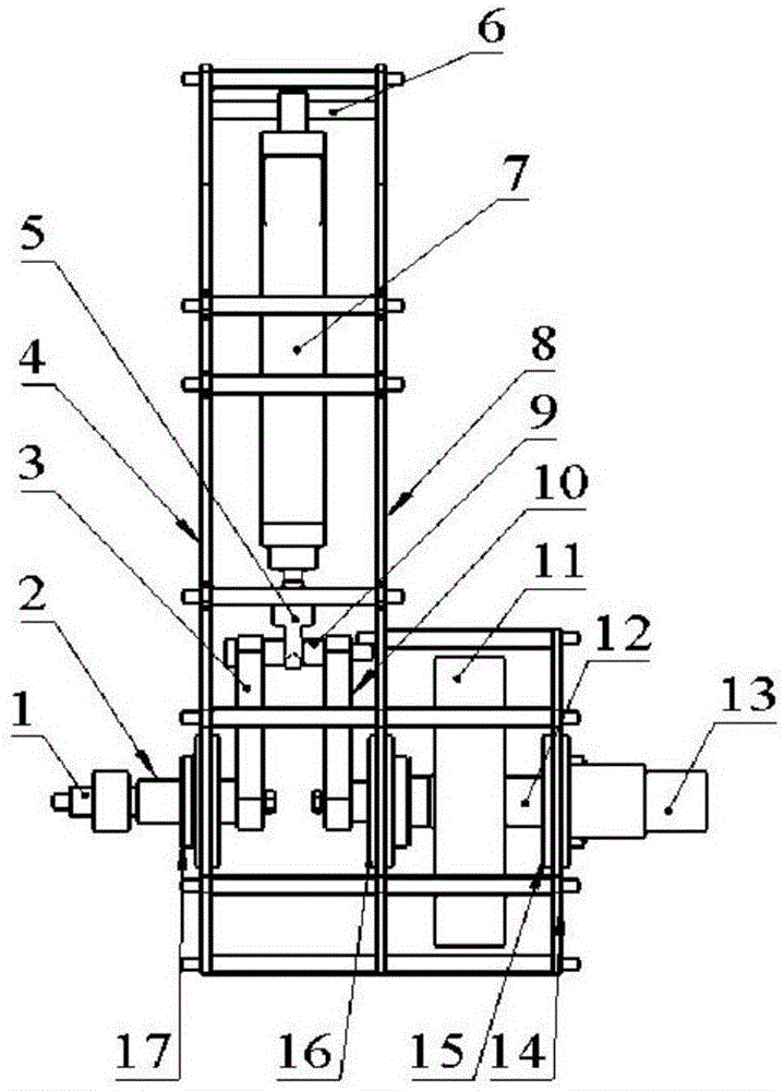
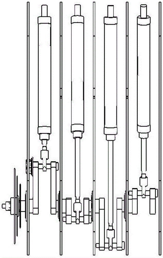
[0018] Combined with Figure 1, Figure 4 to Figure 7 , The cylinder is a single-piston rod tail pin type double-acting cylinder 7, the first bracket plate 4 and the second bracket plate 8 are fixed by stud bolts, and the cylinder is connected to the tail shaft 6 to connect the single-piston rod tail pin type double-acting cylinder. 7 is connected with the combination bracket plate, the cylinder piston rod is connected with the piston rod connecting joint 5 with low thread, the piston rod joint 5 and the connecting shaft of the piston rod are axially positioned and fixed through two small sleeves, and the connecting shaft 9 of the piston rod is connected with the crank 310 turn connection.

[0019] The cylinder piston rod connection joint 5 is installed into the piston rod connection shaft 9, two cranks 310 are installed at both ends of the connection shaft, and the other end of the crank is installed into the crankshaft output shaft 1 and the inertia wheel shaft 12 respectivel...


PUM


Abstract

The invention provides a crank type piston pneumatic engine apparatus comprising a plurality of dual-action air cylinders and a plurality of crank power output units connected with adjacent air cylinders, a variable platen, an inertia wheel, and a pressure control loop. Each crank power output unit has a piston rod connection head, a piston rod connection shaft, a first crank, a second crank, a crank output shaft and an inertia wheel shaft; one end of the piston rod connection head is fixedly connected with an air cylinder piston and the other end is fixedly connected with the middle part of the piston rod connection shaft; two ends of the piston rod connection shaft are respectively connected with the upper end of the first crank and the upper end of the second crank via bearings; the lower end of the first crank is connected with the crank output via a bearing; the lower end of the second crank is connected with the inertia wheel shaft via a bearing; the adjacent air cylinders are connected via the crank output shaft or the inertia wheel; the variable platen is arranged the outermost crank output shaft and fixed thereon; the inertia wheel is arranged on the outermost inertial wheel shaft and fixed thereon; and the pneumatic control loop controls the air cylinder to work.

Description

technical field [0001] The invention relates to an engine technology, in particular to a crank-type piston pneumatic engine device. Background technique [0002] According to statistics, the current global daily oil consumption is about 50 million barrels, of which about 50% is used for transportation, of which about 80% is used for automobiles. At present, the world's proven oil reserves, calculated according to the current oil consumption, can only be used for about 40 years. Therefore, if oil is still the only source of power for automobiles, the automobile industry will soon come to an end. On the other hand, automobile exhaust has become the largest source of pollutants such as CO, NOx and CH in large cities in my country. The large amount of carbon dioxide gas emitted by combustion is the main cause of the global greenhouse effect. Incomplete combustion of automobile fuel has also become one of the reasons for the increase of suspended particulate matter in the air....

Claims


Application Information

Patent Timeline
Patent Type & Authority Applications(China)
IPC IPC(8): F02B75/00F02B77/00
CPCF02B75/00F02B77/00
Inventor 潘孝斌周鑫万云端王叶奔儒谈乐斌
Owner NANJING UNIV OF SCI & TECH
Why Eureka
Try Eureka