
Tray device for engine assembly line

An assembly line and engine technology, which is applied to assembly machines, metal processing equipment, manufacturing tools, etc., can solve the problems of time cost, difficulty, and occupational diseases, and improve the convenience of operation, ensure health and safety, and eliminate difficult operations. Effect

Inactive Publication Date: 2017-05-31
GAC HONDA AUTOMOBILE CO LTD
View PDF6 Cites 3 Cited by
  • Summary
  • Abstract
  • Description
  • Claims
  • Application Information

AI Technical Summary

Problems solved by technology

[0003] Yet this tray locking mechanism has the following two problems: one, it needs to operate the locking mechanism handle when unlocking, which is more time-consuming. The cycle takes 100 seconds, resulting in an invalid time cost; second, because the height of the assembly line will change with the change of the working position, the pallet will also change accordingly
When the tray is at a low position, the staff who operate the tray rotation need to bend down to operate the unlocking handle. The bending operation is a difficult operation, which is prone to occupational diseases and endangers the health of the staff.

Method used


Image

  • Tray device for engine assembly line
  • Tray device for engine assembly line

Examples


Embodiment Construction

[0021] The following will clearly and completely describe the technical solutions in the embodiments of the present invention with reference to the accompanying drawings in the embodiments of the present invention. Obviously, the described embodiments are only some of the embodiments of the present invention, not all of them. Based on the embodiments of the present invention, all other embodiments obtained by persons of ordinary skill in the art without creative efforts fall within the protection scope of the present invention.

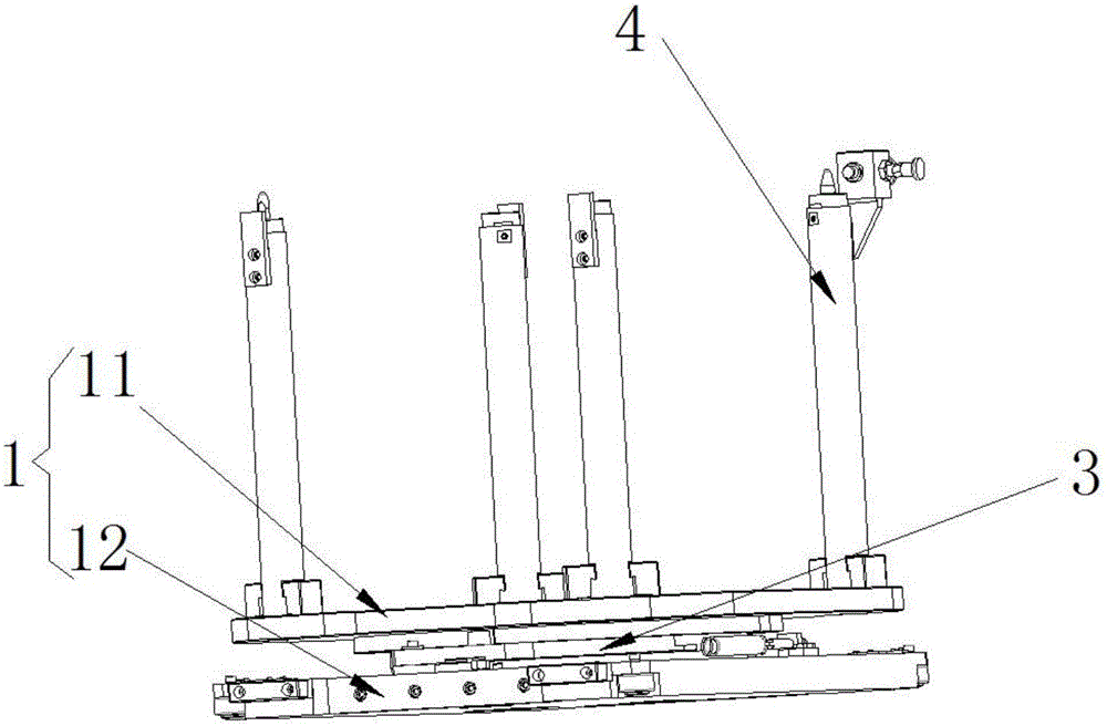
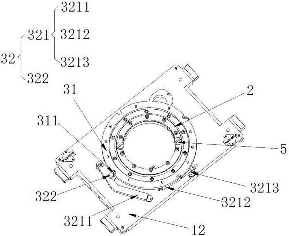
[0022] The pallet device of the engine assembly line of the preferred embodiment of the present invention, as figure 1 As shown, it includes a tray 1, a bearing 2 and a positioning assembly 3, the bearing 2 is installed in the tray 1, and the center point of the bearing 2 is on the same axis as the center point of the tray 1; The positioning assembly 3 is fixedly installed in the tray 1. The positioning assembly 3 includes a positioning disc 31 and a ...


PUM


Abstract

The invention provides a tray device for an engine assembly line. The tray device comprises a tray, a bearing and a positioning component. The bearing is mounted in the tray, and a center point of the bearing and a center point of the tray are coaxial. The positioning component is fixedly mounted in the tray and comprises a positioning plate and a locking mechanism, the positioning plate sleeves the outer periphery of the bearing, the outer edge of the positioning plate is provided with a plurality of grooves peripherally, the locking mechanism comprises a pressing mechanism and projections matched with the grooves, and the projections are arranged on the pressing mechanism to enable the projections to have an elastic force for constantly pressing towards the radial direction of the positioning plate. By structural adoption of the positioning component and the bearing, the positioning plate of the positioning component is provided with the grooves for positioning and fixing of the tray at different stations, invalid operation labor hours for control handle operation and the like of workers are avoided, and difficult operations are eliminated.

Description

technical field [0001] The invention relates to an engine assembly line device, in particular to a pallet device of the engine assembly line which realizes self-locking when stopped. Background technique [0002] At present, the pallet locking mechanism of the engine assembly line at home and abroad generally adopts the handle to control the locking. When the pallet rotates, the staff will unlock the pallet locking mechanism by operating the handle. At this time, after the pallet is rotated in place, it will be locked manually. . [0003] Yet this tray locking mechanism has the following two problems: one, it needs to operate the locking mechanism handle when unlocking, which is more time-consuming. The cycle needs 100 seconds, resulting in an invalid time cost; second, because the height of the assembly line will change with the change of the working position, the pallet will also change accordingly. When the tray is at a low position, the staff who operate the tray rotat...

Claims


Application Information

Patent Timeline
Patent Type & Authority Applications(China)
IPC IPC(8): B23P21/00
CPCB23P21/004
Inventor 郑光奖王军超杨健黄小龙
Owner GAC HONDA AUTOMOBILE CO LTD
Learn More