A kind of self-generating device and wireless switch

A technology of self-generating and installing slots, applied in the direction of electromechanical devices, electrical components, etc., can solve the problem of small power generation, and achieve the effect of increasing magnetic flux and avoiding magnetic leakage

Active Publication Date: 2020-02-04
NINGBO BULL ELECTRIC CO LTD
View PDF1 Cites 0 Cited by
  • Summary
  • Abstract
  • Description
  • Claims
  • Application Information

AI Technical Summary

Problems solved by technology

[0004] The purpose of the present invention is to provide a self-generating device and a wireless switch to solve the problem that the self-generating device in the prior art has a relatively small amount of power generation

Method used


Image

  • A kind of self-generating device and wireless switch
  • A kind of self-generating device and wireless switch
  • A kind of self-generating device and wireless switch

Examples


Embodiment 1

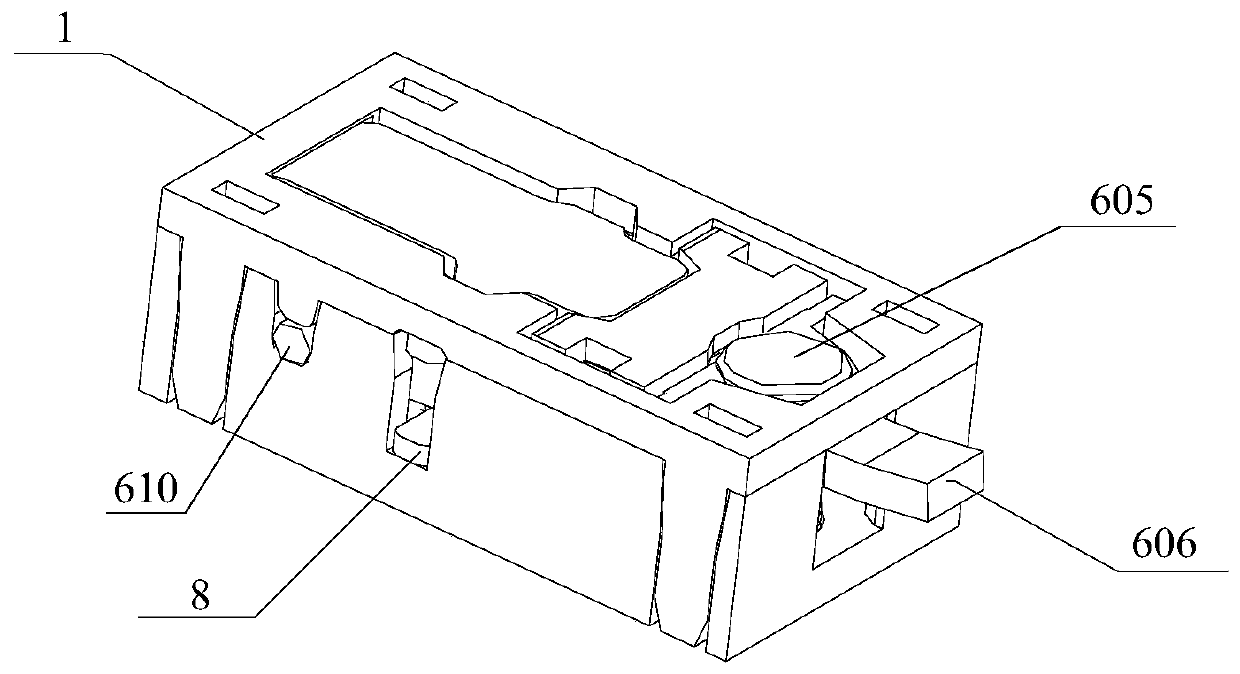
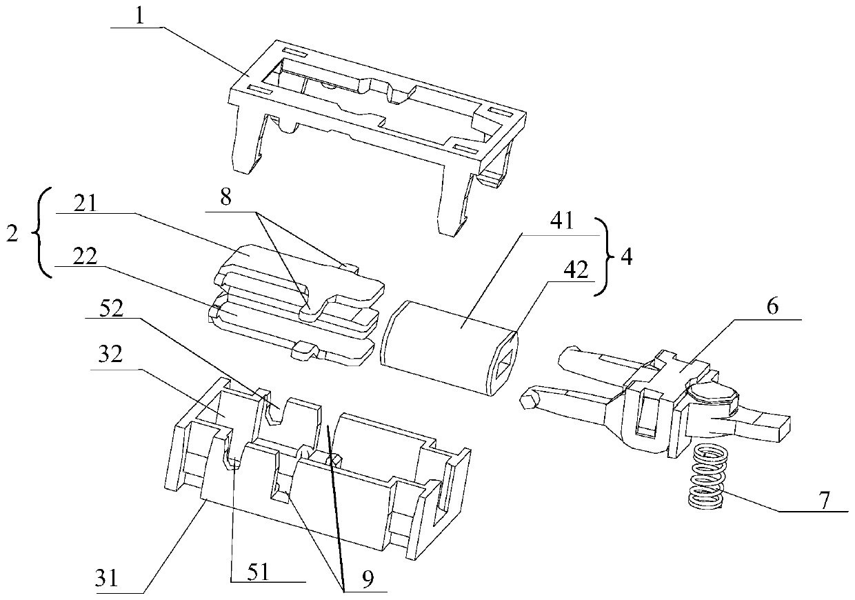
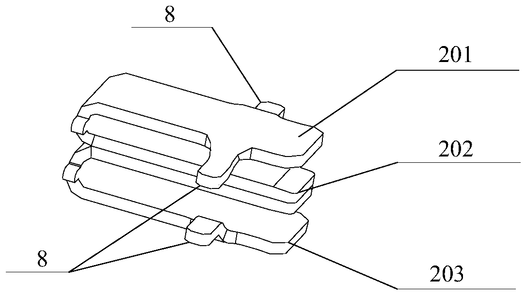
[0044] See figure 2 , image 3 , Figure 4 , Image 6 with Figure 7 The self-generation device provided by the embodiment of the present invention includes a base 31 and a magnetic field generating unit installed on the base 31. The magnetic field generating unit includes an E-shaped iron core 2, an air-core coil assembly 4, and a magnetic contact 60. The E-shaped iron core 2 includes a base 200 and a first extension 201, a middle extension 202, and a second extension 203 respectively provided on the base 200. The hollow coil assembly 4 is sleeved on the middle extension 202. The self-generating device includes a In the first state and the second state; in the first state, the magnetic contact 60 is in contact with the first protrusion 201 and the intermediate protrusion 202 respectively; in the second state, the magnetic contact 60 is in contact with the second protrusion respectively 203 is in contact with the intermediate protrusion 202;

[0045] The extension direction of ...

Embodiment 2

[0074] The present invention also provides a wireless switch, including the self-generating device provided in the above embodiment.

[0075] Compared with the prior art, the beneficial effects of the wireless switch provided by the embodiments of the present invention are the same as the beneficial effects of the self-generating device provided by the above technical solutions, and will not be repeated here.

[0076] Among them, the wireless switch can provide enough power to control the 86-type wall switch of the lamp; and the self-generating device provided by the above embodiment can not only be installed under a single 86-type multi-position wall switch, but also can be installed in all small, compact, And among the power-consuming switches.

[0077] In the description of the foregoing embodiments, specific features, structures, materials, or characteristics may be combined in any one or more embodiments or examples in an appropriate manner.


PUM


Abstract

The invention discloses a self-generating and a wireless switch, relates to the technical field of wireless switches, and solves a problem that a self-generating device in the prior art is not sufficient in power generation. The device comprises a pedestal and a magnetic field generation unit disposed on the pedestal. The magnetic field generation unit comprises an E-shaped iron core, a hollow coil assembly, and a magnetic conduction contact. The E-shaped iron core comprises a basic body, a first stretch-out body, a central stretch-out body and a second stretch-out body, wherein the first stretch-out body, the central stretch-out body and the second stretch-out body are disposed on the basic body. The hollow coil assembly sleeves the central stretch-out body, and the length of the central stretch-out body in the Z-axis direction is less than the length of the first stretch-out body in the Z-axis direction and the length of the second stretch-out body in the Z-axis direction. The device is used for the wireless switch.

Description

Technical field [0001] The present invention relates to the technical field of wireless switches, in particular to a self-generating device and a wireless switch. Background technique [0002] The multi-position wall rocker switch is a switch installed on the wall and used to control the lamp. Because the power cord of the switch needs to be connected to the control circuit, the installation position of the multi-position wall rocker switch is affected by the power supply position. Restrictions limit the scope of application of the multiple wall rocker switches. Therefore, the multiple wall rocker switches are gradually being replaced by wireless switches. [0003] At present, in the prior art, the hand-pressed self-power generation device is applied to the wireless switch to provide the required electric energy for the wireless switch in operation. The Chinese patent CN201320452511.8 discloses a self-generating device, which uses the principle of electromagnetic power generation ...

Claims


Application Information

Patent Timeline
Patent Type & Authority Patents(China)
IPC IPC(8): H02K35/02
CPCH02K35/02
Inventor 田赡民张希伟王卓远张云旆
Owner NINGBO BULL ELECTRIC CO LTD
Why Eureka
Try Eureka