
Lug bending structure and battery cell reshaping device with lug bending structure

A reshaping device and a technology for tabs, which are applied in electrode manufacturing, electrolyte storage battery manufacturing, non-aqueous electrolyte storage batteries, etc., can solve the problems of inconsistent tab inversion, increased internal resistance, poor flatness, etc., and prevent tabs from falling. The effect of inconsistent direction, reduced internal resistance, and low overcurrent temperature

Pending Publication Date: 2017-05-24
ZHUHAI GREE INTELLIGENT EQUIP CO LTD +1
View PDF10 Cites 5 Cited by
  • Summary
  • Abstract
  • Description
  • Claims
  • Application Information

AI Technical Summary

Problems solved by technology

At present, the short lifespan of soft-pack batteries in the power battery industry can no longer meet the use standards of electric buses, making cylindrical batteries the core of the current industry. However, the problem of virtual welding in the welding process of cylindrical batteries after winding has been difficult to completely solve. At present, the main use of The cell is reshaped to ensure the welding quality. The method of reshaping is to bend the tab at the end of the cell. The bent tab is easier to weld with the plate
The existing battery shaping device adopts a fixed rice-shaped mold, which moves in the axial direction at both ends of the battery, thereby bending the tabs. Using a fixed rice-shaped mold to shape the battery will cause post-shaping poles. Inconsistent ears and poor flatness will affect the subsequent welding process of electric cores, which will easily cause false welding, resulting in increased internal resistance and severe heat generation.

Method used


Image

  • Lug bending structure and battery cell reshaping device with lug bending structure
  • Lug bending structure and battery cell reshaping device with lug bending structure
  • Lug bending structure and battery cell reshaping device with lug bending structure

Examples


Embodiment Construction

[0034] The present invention is described below based on examples, but the present invention is not limited to these examples.

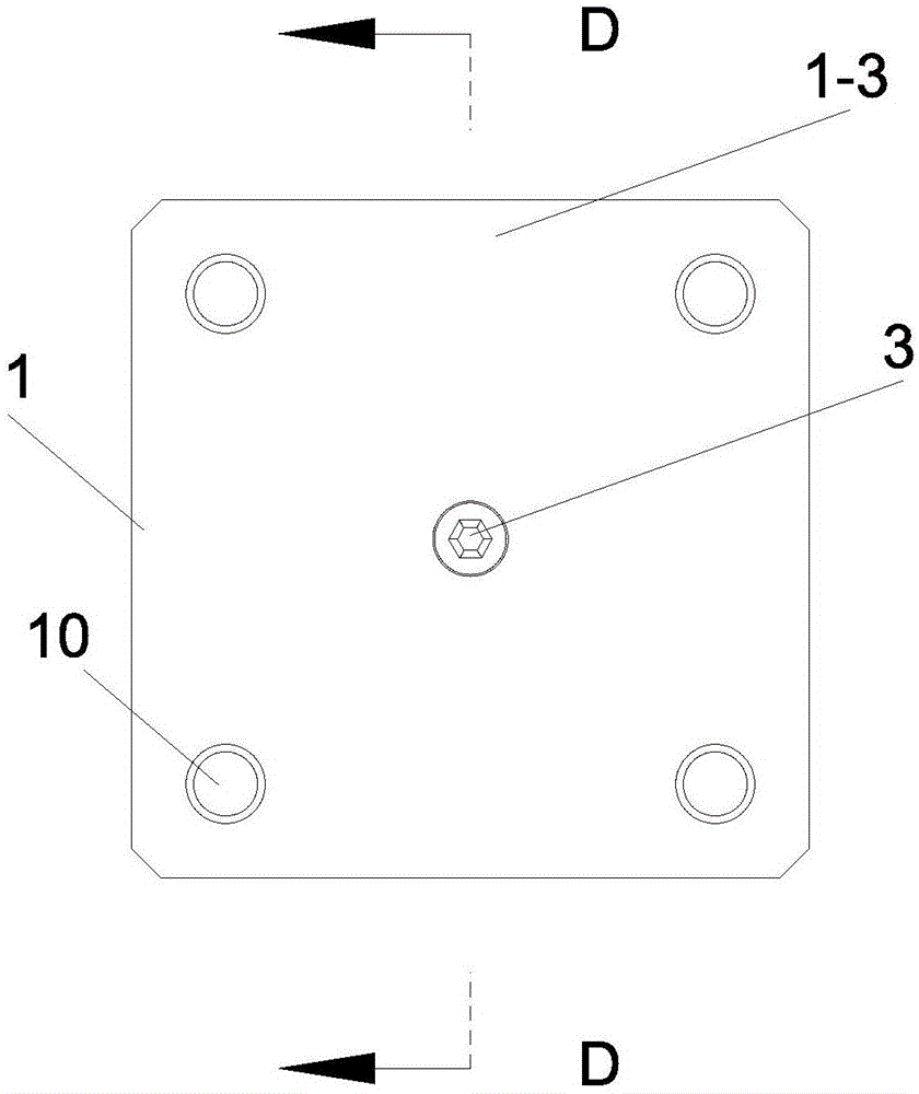
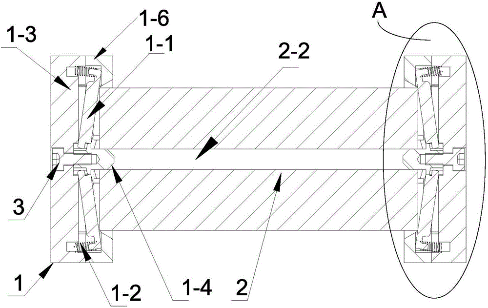
[0035] Such as Figure 1-3 As shown, the present invention provides a cell shaping device, which includes two sets of lug bending structures 1 and a first driver (not shown in the figure, preferably a cylinder), and the cells 2 that need to be shaped are arranged in the two groups. Among the tab bending structures 1, the tab bending structure 1 includes extruding parts, and the first driver drives two sets of tab bending structures 1 to move, so that the extruding parts bend the tabs at both ends of the battery cell 2 . The extruding surface of the existing extruding part is arranged parallel to the end surface of the electric core 2. When extruding, the extruding surface is simultaneously extruded with the end surface of the electric core 2, and the direction of the tab on the end surface of the electric core 2 is different. Certainly, therefore, ...


PUM


Abstract

The invention provides a lug bending structure and a battery cell reshaping device with the lug bending structure. The lug bending structure is used for bending lugs on two ends of a battery cell, and comprises a main body, and an extrusion part arranged on the main body, wherein the extrusion part is characterized in that when the lug bending structure is used for bending, an inner side of a radial direction or an outer side of the radial direction of the extrusion part firstly press against the end part of a radial direction of the battery cell, and the extrusion part can press the lugs from one side of the radial direction to the other side of the radial direction along the radial direction of the battery cell on the end part of the battery cell. According to the lug bending structure provided by the invention, the extrusion part sequentially presses the lugs from one side to the other side along the radial direction on the end part of the battery cell, so that the problems of inconformity in felling directions of the lugs and poor smoothness after the battery cell is reshaped are effectively solved, and a follow-up welding process has no insufficient welding, reduced internal resistance and low overcurrent temperature.

Description

technical field [0001] The invention relates to the field of batteries, in particular to a lug bending structure and a cell shaping device having the same. Background technique [0002] With the development of electric bus and lithium battery industry, the service life and capacity density of batteries have always attracted much attention. At present, the short lifespan of soft-pack batteries in the power battery industry can no longer meet the use standards of electric buses, making cylindrical batteries the core of the current industry. However, the problem of virtual welding in the welding process of cylindrical batteries after winding has been difficult to completely solve. At present, the main use of The cell is reshaped to ensure the welding quality. The method of reshaping is to bend the tab at the end of the cell. The bent tab is easier to weld with the plate. The existing battery shaping device adopts a fixed rice-shaped mold, which moves in the axial direction at ...

Claims


Application Information

Patent Timeline
IPC IPC(8): H01M4/04H01M10/058
CPCH01M4/04H01M10/058Y02E60/10Y02P70/50
Inventor 双超军何军弟卢强马勇军尹勋举杨胜提蔡龙彪
Owner ZHUHAI GREE INTELLIGENT EQUIP CO LTD
Learn More