Demonstration device showing direction of frictional force

A demonstration device and friction technology, which is applied in the field of physics teaching demonstration equipment, can solve problems such as inability to demonstrate clearly, and achieve the effect of simple structure, convenient operation and good stability

Inactive Publication Date: 2017-05-24
欧阳霖
View PDF0 Cites 0 Cited by
  • Summary
  • Abstract
  • Description
  • Claims
  • Application Information

AI Technical Summary

Problems solved by technology

At present, many scholars have also noticed this difficulty and have designed many schemes, but they have not been able to demonstrate clearly in class, so that students have a more intuitive understanding

Method used


Image

  • Demonstration device showing direction of frictional force
  • Demonstration device showing direction of frictional force
  • Demonstration device showing direction of frictional force

Examples


Embodiment 1

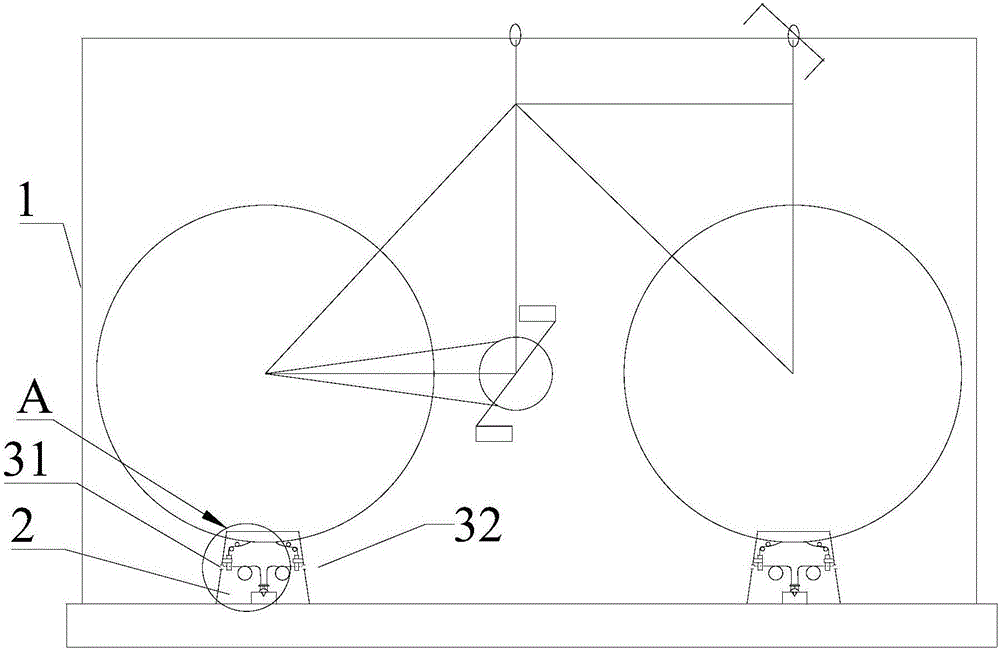
[0056] Please refer to Figure 1 to Figure 6 , the first embodiment of the present invention is: please combine figure 1 with figure 2 , a demonstration device showing the direction of friction force, comprising a bracket 1, a bicycle and two movable friction devices 2 respectively located under the front and rear wheels of the bicycle (the movable friction device 2 is set on the bicycle tire), and the bicycle can slide It is arranged on the bracket 1. In this embodiment, a suspension ring is respectively arranged at the bicycle handle and the seat, and the bicycle is hoisted on the bracket 1 by using the suspension ring.

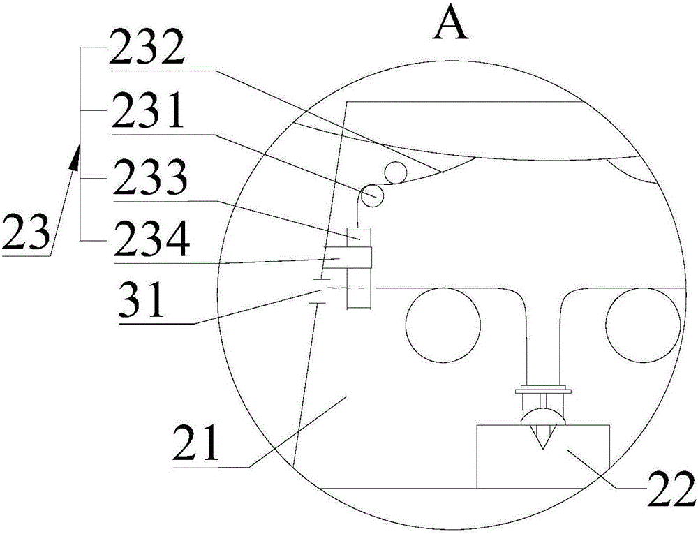
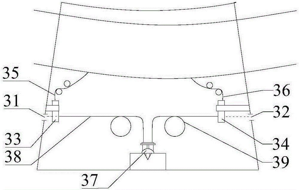
[0057] Please combine figure 1 with figure 2 The movable friction device 2 includes a casing 21, a first laser emitting device 22 and two shading assemblies 23, and the first laser emitting device 22 and two shading assemblies 23 are located inside the casing 21; the shading assembly 23 includes guide wheels 231, Stay cord 232 and shade 233, guide whe...

Embodiment 2

[0072] Please refer to Figure 7 to Figure 12 , Embodiment 2 of the present invention is an improvement made on the basis of Embodiment 1. The biggest difference from Embodiment 1 is that the demonstration device provided by Embodiment 2 can not only display the direction of the friction force on the bicycle, but also display the The direction of the friction force on the ground during the friction process, specifically: please combine Figure 7 with Figure 8 , the demonstration device also includes two chassis friction devices 4, and the two movable friction devices 2 are respectively arranged on the two chassis friction devices 4 and can be slidably arranged along the traveling direction of the bicycle. The chassis friction device 4 includes a cabinet body 41, a second The laser emitting device 42 and two shielding assemblies 43, the second laser emitting device 42 and the two shielding assemblies 43 are arranged inside the cabinet body 41;

[0073] Such as Figure 8 As ...


PUM


Abstract

The invention discloses a demonstration device showing a direction of a frictional force. The demonstration device comprises a bracket, a bicycle, and two movable friction devices which are arranged under a front wheel and a rear wheel of the bicycle separately, wherein the bicycle is arranged on the bracket in a slidable manner; each movable friction device comprises a box body, a first laser emitting device and two light shading assemblies, and the first laser emitting device and the two light shading assemblies are arranged inside the box body; each light shading assembly comprises a guide wheel, a pull rope and a light shading curtain, the guide wheel is fixed on the side wall of the box body, one end of the pull rope is connected with the light shading curtain, the other end of the pull rope is fixed on a bicycle tyre, and the variation of states of the bicycle tyre drives the light shading curtain to ascend and descend; and at the same moment, first laser and second laser irradiate on the corresponding light shading curtains separately, or one of the first laser and the second laser emits out from the box body. The demonstration device displays the rolling friction direction clearly through controlling emitting of the laser by means of the light shading assemblies according to the feature that frictional force directions of the front wheel and the rear wheel are different when the bicycle is being ridden and pushed.

Description

technical field [0001] The invention relates to physics teaching and demonstration equipment, in particular to a teaching and demonstration experiment device for displaying the direction of friction force. Background technique [0002] Friction is one of the emphases and difficulties of high school physics teaching content. Among them, pure rolling friction is static friction, and the uncertainty of its direction is even more difficult for students to understand. The best way to break through this difficulty is to allow students to explore independently and gain personal experience through experimental methods. At present, many scholars have also noticed this difficulty and have designed many solutions, but they have not been able to clearly demonstrate it in class, so that students can have a more intuitive understanding. [0003] The moving process of tires is a typical pure rolling friction. It will be a good choice to use a bicycle as an experimental body and other equ...

Claims


Application Information

Patent Timeline
Patent Type & Authority Applications(China)
IPC IPC(8): G09B23/10
CPCG09B23/10
Inventor 欧阳霖陈新光
Owner 欧阳霖
Why Eureka
Try Eureka