


Quick Research
Generate reliable direction feasibility study reports for your R&D in just a few steps.

Technical Q&A
Discover and master advanced knowledge NOW. Basics, ideas, possibilities, all at once.

Find Solutions
As an expert in R&D theories, this can generate solutions to your technical problems instantly.

Evaluate Feasibility
Analyze your overall solution with one click, know your potential R&D risks in advance.

Monitor Landscape
Get weekly tech updates, stay abreast of the latest tech innovations and key insights.
Path planning method for inspection robot based on map grid and potential field method for obstacle avoidance
An inspection robot and path planning technology, which is applied in the direction of instruments, two-dimensional position/channel control, vehicle position/route/height control, etc., can solve the problems of prolonged robot inspection time and low path planning efficiency, and improve Complete efficiency, improve effectiveness, and shorten path distance
- Summary
- Abstract
- Description
- Claims
- Application Information
AI Technical Summary
Problems solved by technology
Method used
Image

Examples
Embodiment 1
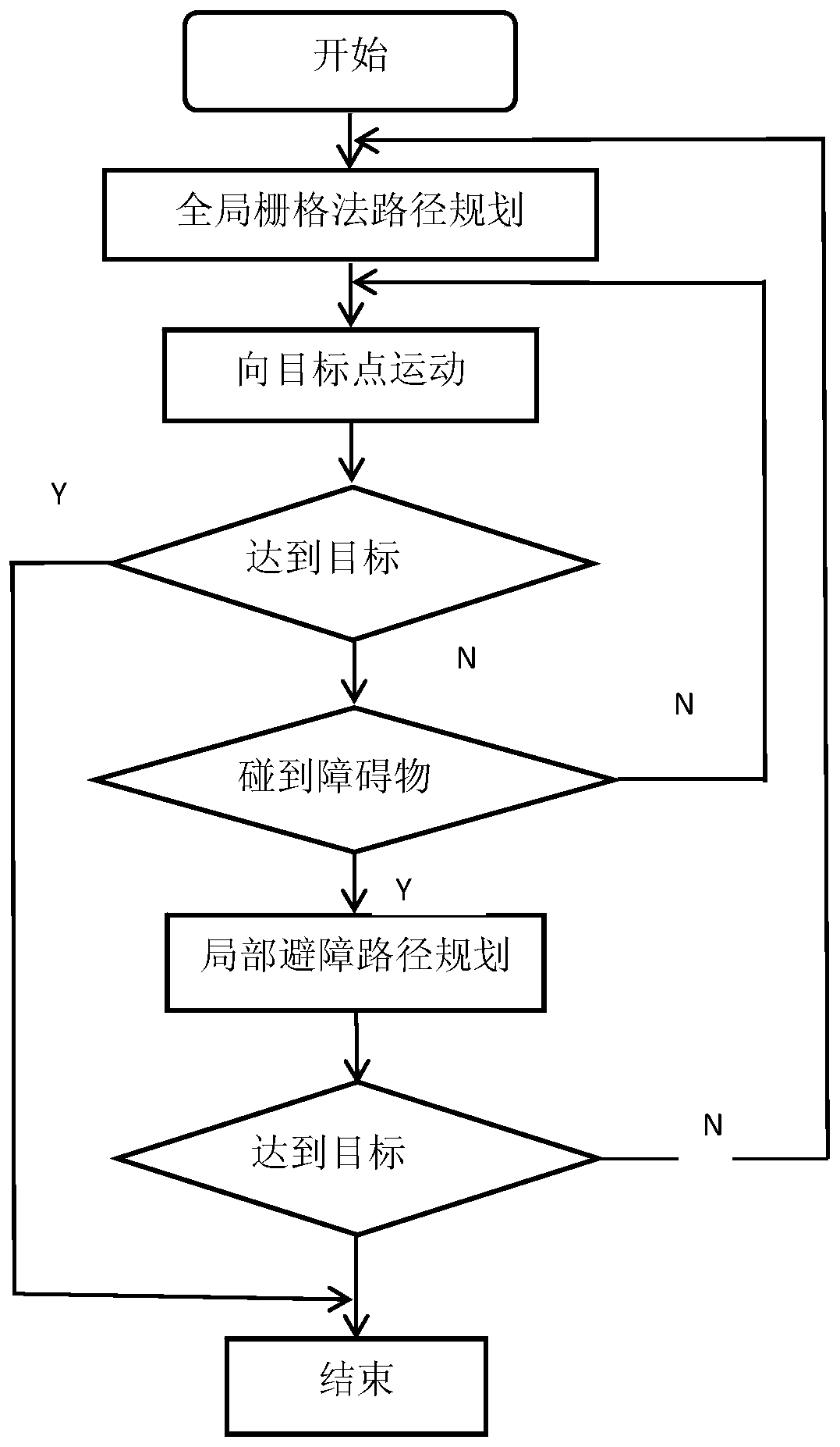
[0068] combine figure 1 , figure 1 It is the overall flow chart of the present invention. First, global path planning is carried out, and a global optimal path from the starting point to the target point is obtained by using the grid method; according to this optimal path, it moves to the target point, and judges whether it encounters an obstacle. If not, it continues to move to the target point. Otherwise, carry out local obstacle avoidance path planning; for local obstacle avoidance path planning, use the artificial potential field method with variable parameters for obstacle avoidance path planning, and judge whether to reach the target point, if not, continue to move to the target point, otherwise end.
Embodiment 2
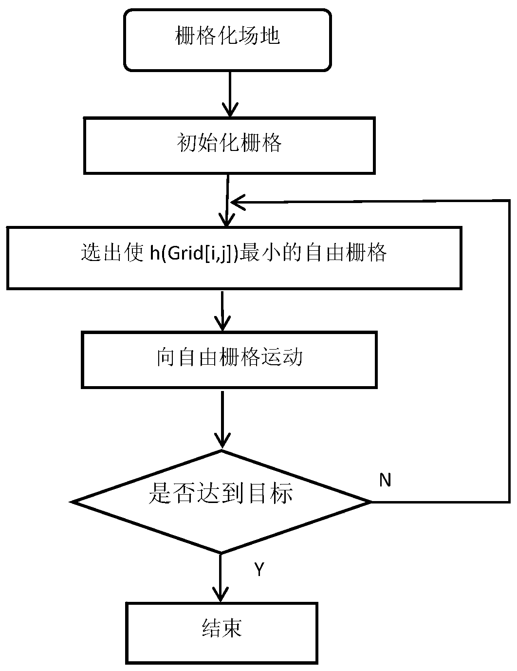
[0070] combine figure 2 , figure 2 This is the flow chart of the global path planning program of the present invention. First, grid the site to determine the target point, obstacles and the grid where the robot itself is located; initialize the grid, mark the grid with obstacles as 1, and mark the free grid as 0; search for the adjacent grids of the robot, select From the free grid, define the evaluation function h(Grid[i,j]) to calculate the distance between the center point of this grid and the center point of the target grid: Grid[i,j] is the coordinates of the grid adjacent to the grid where the robot is located, and goal represents the grid coordinates of the target point; compare the h(Grid[i,j]) values of each grid, and select the [i,j]) the smallest grid Grid[i,j] min , set Grid[i,j] min The grid is used as the grid that the robot will move to next; it is judged whether the robot has reached the target point, if not, it will continue to search the adjacent gri...
Embodiment 3
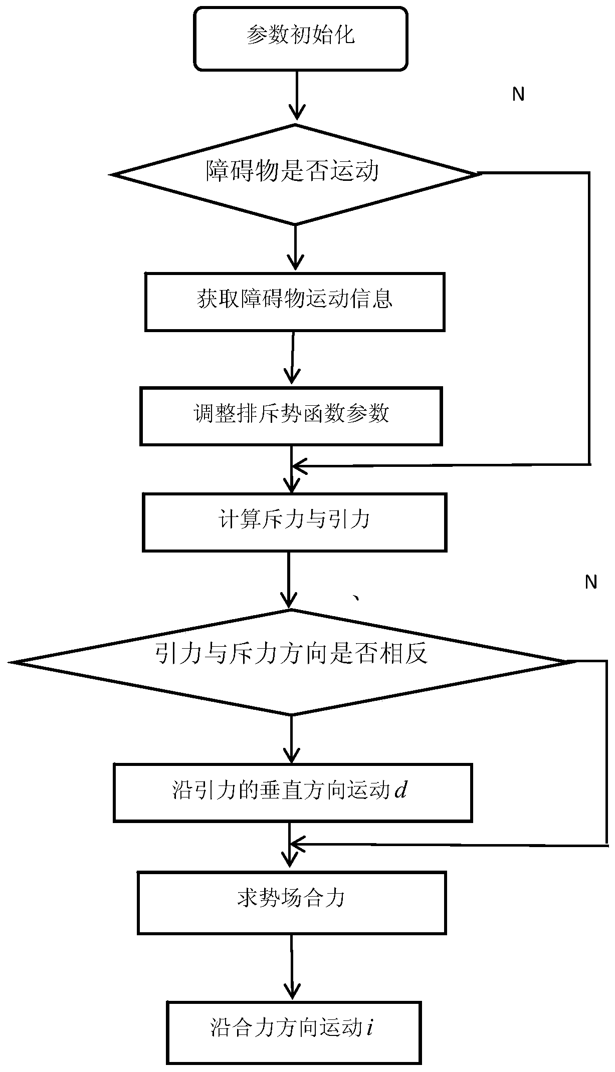
[0072] combine image 3 , image 3 This is the flow chart of the local obstacle avoidance path planning procedure of the present invention. First initialize the parameters of the potential field function, d1: the distance between the robot's current position and the obstacle observed by the lidar, k1: the repulsion weighting coefficient, which is temporarily set to 0.5, and is adjusted according to the obstacle avoidance effect during the debugging process. d2: The distance between the robot's current position and the target position point, k2: The gravity weighting coefficient, temporarily set to 0.5, and the specific adjustment is made according to the obstacle avoidance effect during the debugging process; then the global lidar sensor is used to judge the encountered obstacles Whether to move, if not, calculate the repulsive force and gravitational force directly according to the initialized parameters; otherwise, obtain the motion vector of the obstacle and the relative p...
PUM
 Abstract
Description
Claims
Application Information
 - R&D Engineer
- R&D Manager
- IP Professional
- Industry Leading Data Capabilities
- Powerful AI technology
- Patent DNA Extraction
Browse by: Latest US Patents, China's latest patents, Technical Efficacy Thesaurus, Application Domain, Technology Topic, Popular Technical Reports.
© 2024 PatSnap. All rights reserved.Legal|Privacy policy|Modern Slavery Act Transparency Statement|Sitemap|About US| Contact US: help@patsnap.com