


Quick Research
Generate reliable direction feasibility study reports for your R&D in just a few steps.

Technical Q&A
Discover and master advanced knowledge NOW. Basics, ideas, possibilities, all at once.

Find Solutions
As an expert in R&D theories, this can generate solutions to your technical problems instantly.

Evaluate Feasibility
Analyze your overall solution with one click, know your potential R&D risks in advance.

Monitor Landscape
Get weekly tech updates, stay abreast of the latest tech innovations and key insights.
Pulse signal detection method based on Windows system function and multi-thread technology
A multi-thread technology and pulse signal technology, which is applied in the field of pulse signal detection, can solve the problems of high cost, small number of timing/counter card channels, long development cycle of FPGA detection pulse signal pulse width, etc., and achieve the effect of ensuring detection accuracy
- Summary
- Abstract
- Description
- Claims
- Application Information
AI Technical Summary
Problems solved by technology
Method used
Image

Examples
specific Embodiment approach 1
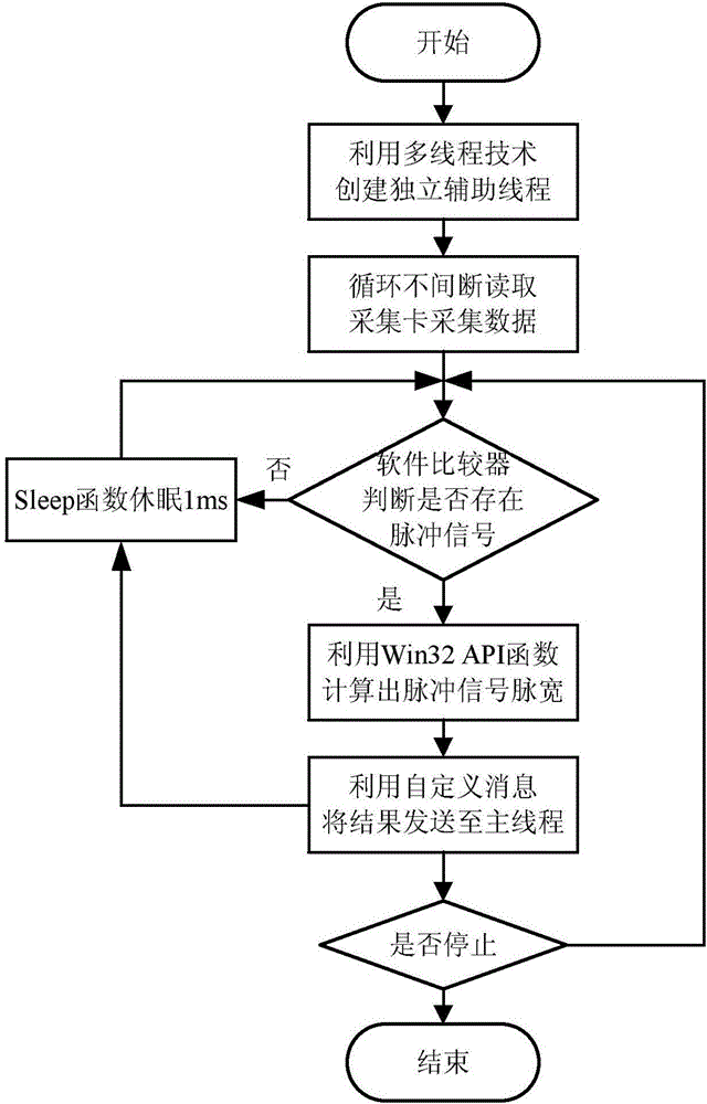
[0021] Specific implementation mode one: combine figure 1 Describe this embodiment, the specific process of the pulse signal detection method based on Windows system function and multi-thread technology of this embodiment is:
[0022] Step 1, start, based on the VC environment, use multi-threading technology to create and start an independent auxiliary thread;
[0023] Step 2, read the data collected by the AD card or the digital IO card continuously in an independent auxiliary thread;
[0024] Step 3. Use a software comparator to judge whether there is a pulse signal in the collected data. If there is a pulse signal, perform step 5; if there is no pulse signal, perform step 4;
[0025] Step 4. In the independent auxiliary thread, the Sleep function sleeps for 1ms, and then executes Step 3;
[0026] Step five, calculate the pulse width and level of the pulse signal, the pulse width and amplitude of the pulse signal or the pulse width, level and amplitude of the pulse signal ...
specific Embodiment approach 2
[0029] Specific embodiment two: the difference between this embodiment and specific embodiment one is: adopt software comparator to judge whether there is pulse signal in the data collected in described step 3, if there is pulse signal, execute step 5; If there is no pulse signal, Execute step 4; the specific process is:
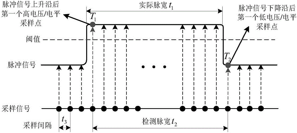
[0030] 1) At the beginning, define the high voltage in the independent auxiliary thread to continuously read the data collected by the AD card (for example, the hardware collects the pulse signal, 10V when there is a pulse signal, 0V when there is no pulse signal, and the low voltage is 0V , the high voltage is 10V;) sampling point count variable N=0;
[0031] 2), judging whether the voltage in the data collected by the AD card is read continuously in an independent auxiliary thread is greater than or equal to the threshold, if yes, execute 3); if not, execute 7);
[0032] The voltage in the collected data includes the high voltage in the collected data and...
specific Embodiment approach 3
[0044] Specific embodiment three: the difference between this embodiment and specific embodiment one or two is that: in the step three, a software comparator is used to judge whether there is a pulse signal in the collected data, if there is a pulse signal, perform step five; if there is no pulse signal, execute step 4; the specific process is:
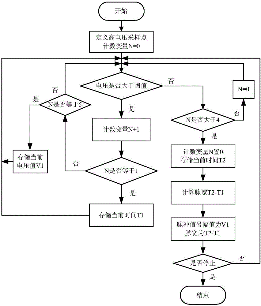
[0045] 1), start, define the high-level sampling point counting variable N=0 in the data collected by the digital IO card;
[0046] 2), judge whether the level in the data collected by the digital IO card is high level (for example, high level is 1, low level is 0;), if yes, perform 3); if not, perform 5);
[0047] 3), the counting variable is N+1, judge whether N is equal to 1, if yes, execute 4); if not, execute 2);
[0048] 4), the sampling point is the first high-level sampling point after the rising edge of the pulse signal, store the current time T1, and execute 2);
[0049] 5), judge whether N is greater than A, if yes, execute...
PUM
 Abstract
Description
Claims
Application Information
 - R&D Engineer
- R&D Manager
- IP Professional
- Industry Leading Data Capabilities
- Powerful AI technology
- Patent DNA Extraction
Browse by: Latest US Patents, China's latest patents, Technical Efficacy Thesaurus, Application Domain, Technology Topic, Popular Technical Reports.
© 2024 PatSnap. All rights reserved.Legal|Privacy policy|Modern Slavery Act Transparency Statement|Sitemap|About US| Contact US: help@patsnap.com