Bracket and construction method of deep trench support

A technology of deep grooves and corbels, which is applied in excavation, infrastructure engineering, construction, etc., can solve the problems of non-reusable use and inconvenient installation of corbels, and achieve the solution of non-reusable use, convenient dismantling, and avoiding construction steps Effect

Active Publication Date: 2017-05-24
SHANGHAI NO 7 CONSTR
View PDF7 Cites 4 Cited by
  • Summary
  • Abstract
  • Description
  • Claims
  • Application Information

AI Technical Summary

Problems solved by technology

[0003] The invention provides a construction method for corbels and deep groove support to solve the problems that the corbels are inconvenient to install and cannot be reused during the construction process of deep groove support

Method used


Image

  • Bracket and construction method of deep trench support
  • Bracket and construction method of deep trench support
  • Bracket and construction method of deep trench support

Examples


Embodiment 1

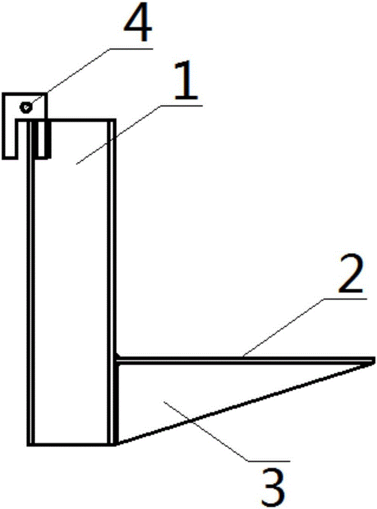
[0031] refer to Figure 1 to Figure 2 , the present embodiment provides a corbel, comprising a vertically arranged I-beam 1, a bottom plate 2, and a reinforcing rib 3, the bottom plate 2 is horizontally arranged and fixed on the lower part of the right side flange of the I-beam 1, the The reinforcing rib 3 is vertically fixed on the bottom of the bottom plate 2 and is vertically fixedly connected with the right side flange of the I-beam 1, and also includes a suspension device 4, and the suspension device 4 is fixed on the left side of the I-beam 1 upper edge.

[0032] A kind of corbel of this embodiment, since the suspension device 4 is arranged on the upper part of the left flange of the I-beam 1, when the corbel is installed, only the corbel needs to be fixed on the top of the steel sheet pile wall through the suspension device 4 , the installation of the corbel can be completed, unnecessary construction steps such as welding are avoided, and the problem of inconvenient co...

Embodiment 2

[0038] refer to Figure 1 to Figure 3 , this embodiment provides a construction method for deep trench support.

[0039] The technical scheme of the construction method of a kind of deep trench support of the present embodiment is as follows:

[0040] A construction method for deep trench support, the steps are as follows:

[0041] In the first step, several steel sheet piles 5 are driven into both sides of the deep trench to be constructed to form steel sheet pile walls on both sides of the deep trench to be constructed, and the top elevations of several steel sheet piles 5 are unified, and the top elevations of the steel sheet piles 5 are uniform Finally, the purlin 6 can be installed horizontally, which strengthens the supporting effect of the purlin 6 on the steel sheet pile wall;

[0042] In the second step, a foundation trench is excavated between the steel sheet pile walls on both sides, and the depth of the foundation trench is greater than the height of the corbel i...


PUM

PropertyMeasurementUnit
Thicknessaaaaaaaaaa

Abstract

The invention provides a bracket and a construction method of a deep trench support so as to solve the problem that the bracket is inconvenient to mount and cannot be repeatedly utilized in the construction process of the deep trench support. Due to the arrangement of a suspending device at the upper part of the left flange of an I steel, when the bracket is mounted, the mounting of the bracket can be finished as long as the bracket is fixed at the top of a steel sheet pile wall through the suspending device, so that unnecessary construction steps, such as welding, are avoided, and the problem of construction inconvenience caused by welding necessity during the mounting of the bracket is solved. As the bracket can be conveniently disassembled after the construction of the deep trench support is finished, the bracket can be cyclically used, and the problem that the existing bracket cannot be repeatedly utilized is solved.

Description

technical field [0001] The invention relates to the current field of deep trench support construction, in particular to a construction method for corbels and deep trench support. Background technique [0002] In the current deep trench support construction, purlins need to be installed inside the steel sheet pile wall to increase the strength of the steel sheet pile wall. Generally speaking, ordinary corbels are used as purlin supports and welded to steel sheet piles. As a result, the installation of the corbel requires on-site welding operations, which is inconvenient for installation, and in the absence of power supply from high-power electrical equipment, it cannot be installed. In addition, once the corbel is welded to death, the corbel cannot be recovered and reused in its original state, which wastes resources. Contents of the invention [0003] The invention provides a construction method for a corbel and a deep trench support to solve the problems that the corbel...

Claims


Application Information

Patent Timeline
IPC IPC(8): E02D17/04E02D5/04E02D5/16
CPCE02D5/04E02D5/16E02D17/04
Inventor 苗得雨方思倩周吉方荣梁军谭江王珏非
Owner SHANGHAI NO 7 CONSTR
Why Eureka
Try Eureka