An Automatic Deburring Device Capable of Realizing Compensation

A deburring, automatic technology, used in grinding drives, grinding/polishing safety devices, grinding machine parts, etc., can solve the problems of component damage, low work efficiency, high labor intensity, etc., to ensure smoothness and stability, simple structure and low cost

Active Publication Date: 2018-12-11
HEFEI INSTITUTES OF PHYSICAL SCIENCE - CHINESE ACAD OF SCI
View PDF7 Cites 0 Cited by
  • Summary
  • Abstract
  • Description
  • Claims
  • Application Information

AI Technical Summary

Problems solved by technology

At present, the commonly used deburring method is to use sandpaper or brush to manually process the products one by one. This manual processing method is labor-intensive, low in work efficiency, and has safety problems. At the same time, it is easy to cause damage to components.

Method used


Image

  • An Automatic Deburring Device Capable of Realizing Compensation
  • An Automatic Deburring Device Capable of Realizing Compensation
  • An Automatic Deburring Device Capable of Realizing Compensation

Examples


Embodiment Construction

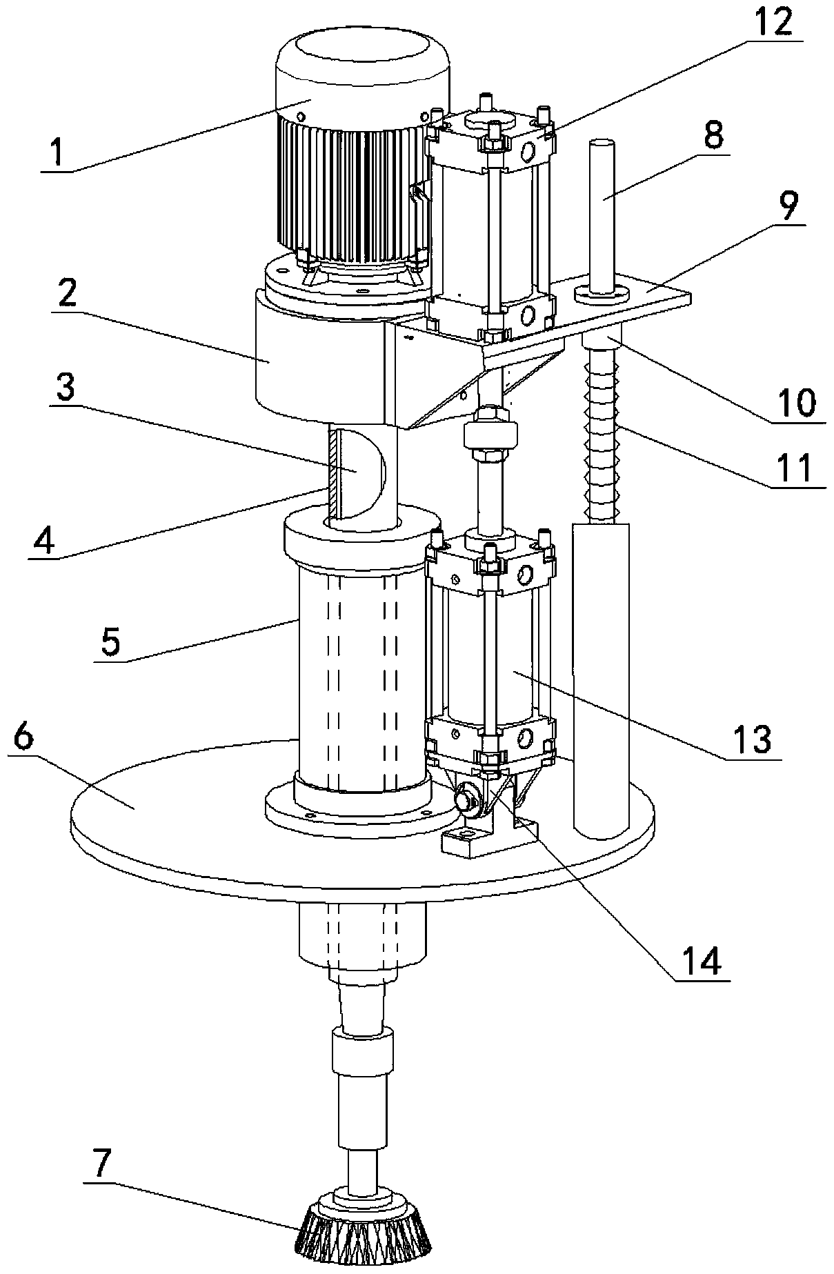
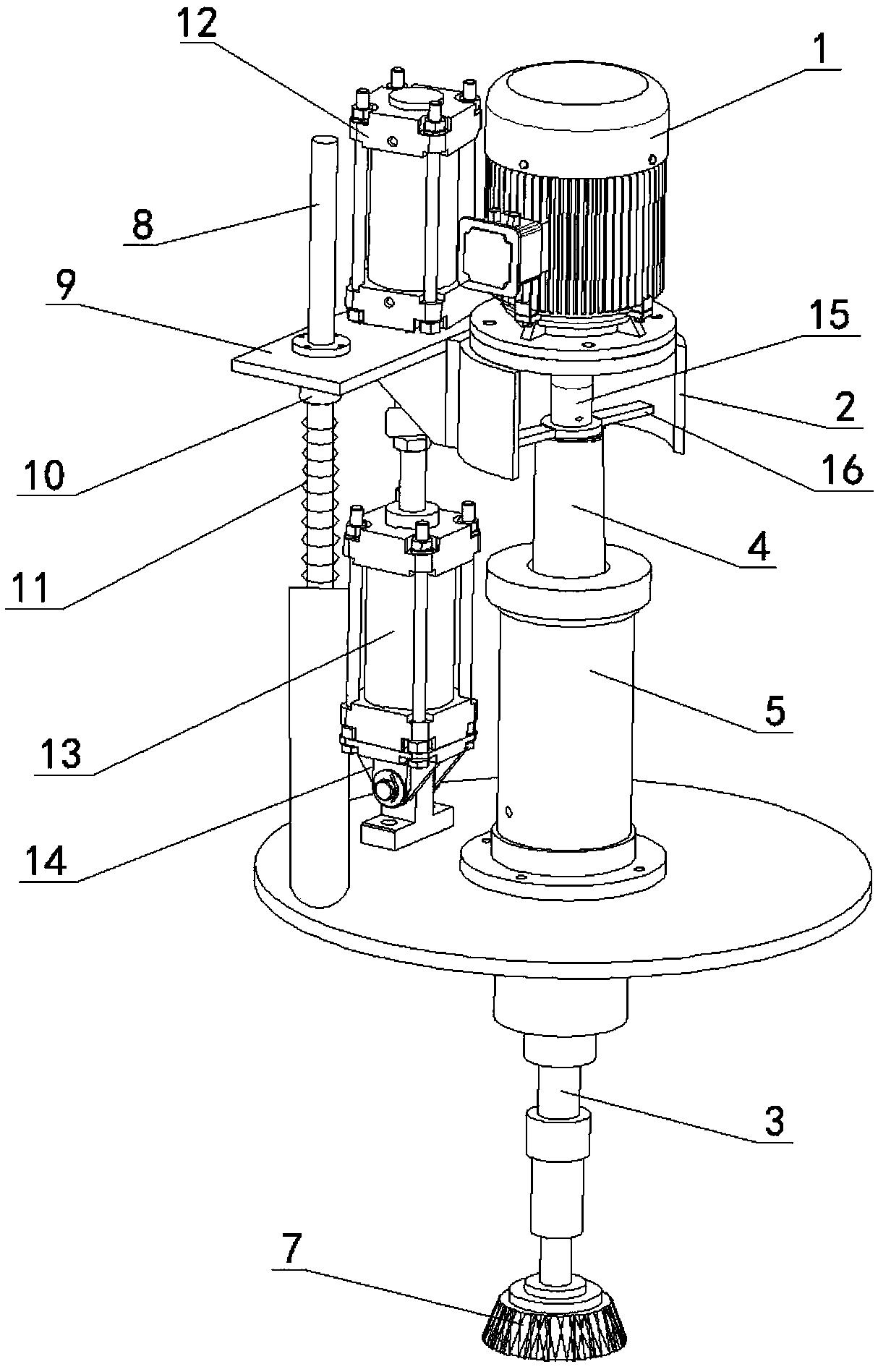
[0023] see figure 1 , figure 2 and image 3 , the structural form of the automatic deburring device that can realize compensation in this embodiment is:

[0024] The motor 1 is fixedly installed on the motor mounting base 2, so that the output shaft of the motor 1 is vertically downward, and the rotating shaft 3 is fixedly connected with the output shaft of the motor 1 through the coupling 15. The bottom shaft end of the shaft is fixedly installed with a brush 7 that can rotate with the rotating shaft, and the fixed guide base 5 is installed on the horizontal base plate 6 .

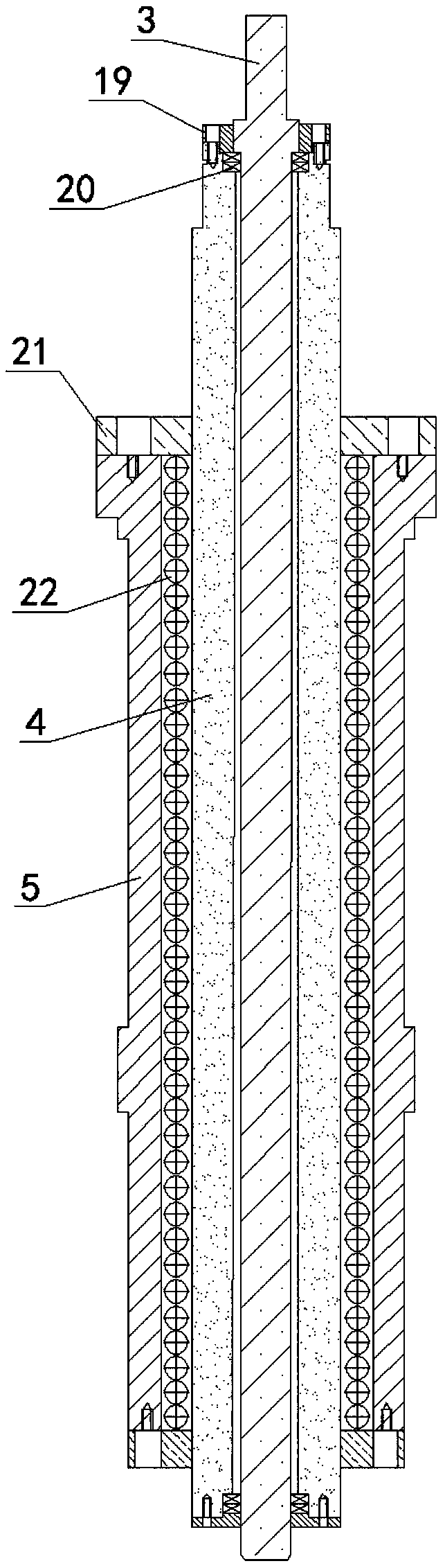
[0025] A hollow guide shaft 4 is arranged between the rotating shaft 3 and the fixed guide seat 5 . The hollow guide shaft 4 is fixedly connected to the motor mounting base 2 . The rotating shaft 3 penetrates the hollow guide shaft 4 and can rotate freely in the hollow guide shaft 4 . The hollow guide shaft 4. Passing through the fixed guide seat 5, the hollow guide shaft 4 can move up and down along ...


PUM


Abstract

The invention discloses an automatic deburring device capable of realizing compensation. The automatic deburring device capable of realizing compensation is characterized in that the output shaft of a motor is vertically downward; a rotating shaft fixedly connected with the output shaft of the motor penetrates through a fixed guide base; a hairbrush which rotates along with the rotating shaft is mounted at the shaft end of the bottom of the rotating shaft; the fixed guide base is mounted on a horizontal base plate; a hollow guide shaft fixedly connected with a motor mounting base is arranged between the rotating shaft and the fixed guide base; the rotating shaft can rotate in the hollow guide shaft; the hollow guide shaft can move up and down along the fixed guide base; a lifting guide base is horizontally arranged on the motor mounting base in an overhanging manner; a lifting cylinder is mounted on the lifting guide base; a compensation cylinder is mounted on the base plate; the lifting cylinder and the compensation cylinder in the coaxial position are fixedly connected, and the ends of a piston rod of the lifting cylinder and the ends of a piston rod of the compensation cylinder are opposite; the motor is driven by the lifting cylinder to vertically rise and fall; and the wearing capacity of the hairbrush is compensated by the compensation cylinder. The automatic deburring device capable of realizing compensation disclosed by the invention is used for performing deburring treatment on the surface of a workpiece, has a compensation function, and can prolong the service life of the hairbrush.

Description

technical field [0001] The present invention relates to a deburring device, more particularly, to a device for deburring the surface of metal products such as stainless steel. Background technique [0002] Deburring the product surface is a necessary procedure in the forming process of some products, especially for stainless steel and other metal products, such as stainless steel pipes, etc., before the product is formed, or before the surface coating and other steps, it is usually necessary to deburr the product. The surface is deburred. At present, the commonly used deburring method is to use sandpaper or a brush to manually process the products one by one. This manual processing method is labor-intensive, low in work efficiency, and has safety problems. At the same time, it is very easy to cause damage to components. SUMMARY OF THE INVENTION [0003] The present invention provides an automatic deburring device that can realize compensation in order to avoid the above-m...

Claims


Application Information

Patent Timeline
Patent Type & Authority Patents(China)
IPC IPC(8): B24B9/04B24B55/00B24B41/00B24B47/14
CPCB24B9/04B24B41/007B24B47/14B24B55/00
Inventor 潘兵李露付卫国夏军邓建新
Owner HEFEI INSTITUTES OF PHYSICAL SCIENCE - CHINESE ACAD OF SCI
Why Eureka
Try Eureka