
Crimping tool structure of electric reactor coil terminal

A terminal crimping and reactor technology, applied in coil manufacturing, circuit/collector parts, circuits, etc., can solve the problems of high current, low production efficiency, rework, etc., to achieve accurate and uniform size, firm and reliable crimping, The effect of high work efficiency

Active Publication Date: 2017-05-17
FUJIAN EVERSTRONG LEGA POWER EQUIP CO LTD
View PDF4 Cites 2 Cited by
  • Summary
  • Abstract
  • Description
  • Claims
  • Application Information

AI Technical Summary

Problems solved by technology

[0007] (5) The current passing through is relatively large, and the crimping between the coil and the terminal must be firm and reliable, otherwise it will cause heat or even burn out
[0008] 1. It is difficult to keep the size requirements right, which will affect the operation of subsequent processes and even cause rework;
[0009] 2. Low production efficiency and high cost

Method used


Image

  • Crimping tool structure of electric reactor coil terminal
  • Crimping tool structure of electric reactor coil terminal
  • Crimping tool structure of electric reactor coil terminal

Examples


Embodiment Construction

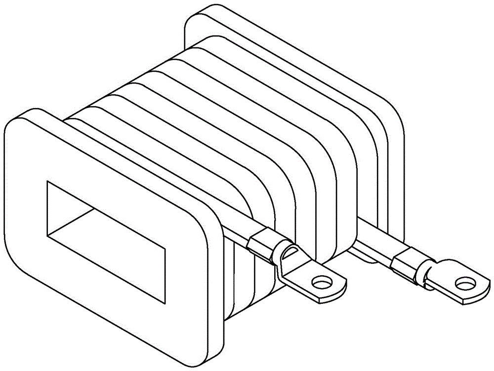
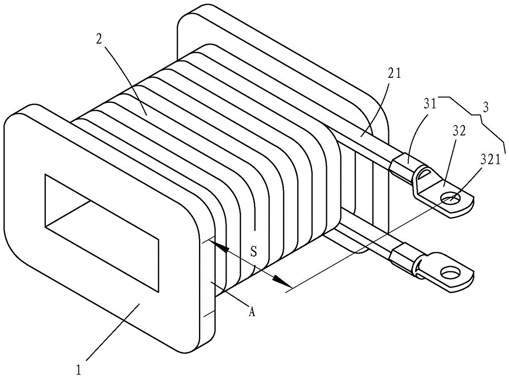
[0035] See Figure 1 and figure 2 As shown, the reactor coil includes a skeleton 1, a coil 2 and a terminal 3, the terminal 3 includes a crimping end 31 and a connecting end 32, the crimping end 31 has an inner hole D, and the connecting end 32 There is a bolt hole 321 on it;

[0036] see again Figure 2-3 with Figure 4 , a reactor coil terminal crimping tooling structure, including a pneumatic press (not shown), a skeleton 1, a coil 2, a terminal 3, an upper tooling body 4, a lower tooling body 5, an upper die 6, a lower tooling body Die 7, a positioning unit 8; the pneumatic press has a piston rod 12; the upper tooling body 4 includes a column 41 and a guide post 42, the upper end of the column 41 is recessed downward to form a The piston rod 12 matches the counterbore 411, and the piston rod 12 is inserted in the counterbore 411; the bottom of the column 41 extends vertically backward with a mounting plate 43, and the top of the guide column 42 is vertically fixed on th...


PUM


Abstract

Disclosed is a crimping tool structure of an electric reactor coil terminal. The crimping tool structure comprises an upper tool body, a lower tool body, an upper pressing die and a lower pressing die, wherein the upper tool body comprises a column body and a guiding column; a counter bore is formed in the upper end plane of the column body; a piston rod is inserted in the counter bore; a mounting plate extends perpendicularly and backwardly at the bottom of the column body; the top of the guiding column is perpendicularly fixed on the mounting plate; the lower tool body comprises a bottom plate, a stand column and a guiding plate; the guiding plate is perpendicularly connected with the upper part of the stand column; a positioning hole is formed in the guiding plate; in a working state, the guiding column is inserted in the positioning hole; the upper pressing die is fixed at the bottom end of the column body, and the bottom end of the upper pressing die concaves inwardly to form a first trapezoid-shaped groove; the lower pressing die is fixed at the top end of the stand column; a second trapezoid-shaped groove is formed in the top end of the lower pressing die; and the first trapezoid-shaped groove and the second trapezoid-shaped groove are formed in a corresponding manner. The crimping tool structure is convenient and safe to operate, accurate and unified in dimensions, firm and reliable in crimping and high in working efficiency.

Description

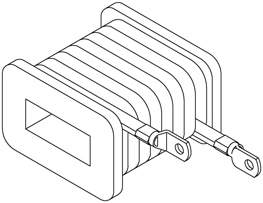
technical field [0001] The invention specifically relates to a reactor coil terminal crimping tooling structure. Background technique [0002] The reactor is mainly composed of an iron core and a coil. The reactor coil includes a skeleton 1, a coil 2 and a terminal 3; the crimping between the coil 2 and the terminal 3 has five major requirements: [0003] (1) The terminals 3 of two different specifications are respectively crimped with matching flat copper (or aluminum) wires. The difference between the two terminals 3 of different specifications lies in: the size of the inner hole D and the center of the bolt hole 321 to the crimping end 31 The distance L between the end faces is different; [0004] (2) Coil 2 has an odd number of layers [such as Figure 1a , Figure 1c as shown] or double-numbered layers (such as Figure 1b , Figure 1d As shown), the outlet positions of the two are different; [0005] (3) There are two crimping methods in different directions between...

Claims


Application Information

Patent Timeline
Patent Type & Authority Applications(China)
IPC IPC(8): H01F41/10H01R43/048
CPCH01F41/10H01R43/048
Inventor 林朝文
Owner FUJIAN EVERSTRONG LEGA POWER EQUIP CO LTD
Learn More