


Quick Research
Generate reliable direction feasibility study reports for your R&D in just a few steps.

Technical Q&A
Discover and master advanced knowledge NOW. Basics, ideas, possibilities, all at once.

Find Solutions
As an expert in R&D theories, this can generate solutions to your technical problems instantly.

Evaluate Feasibility
Analyze your overall solution with one click, know your potential R&D risks in advance.

Monitor Landscape
Get weekly tech updates, stay abreast of the latest tech innovations and key insights.
Many-to-many controlled self-power generation two-way communication device and method
A two-way communication, self-generating technology, applied in program control, comprehensive factory control, electrical program control, etc., can solve problems such as unsightly, large switch structure, non-reusable, etc., to avoid inconvenience and realize smart home. The effect of saving installation cost
- Summary
- Abstract
- Description
- Claims
- Application Information
AI Technical Summary
Problems solved by technology
Method used
Image

Examples
Embodiment 1
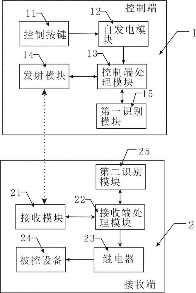
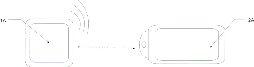
[0045] see figure 2 , the accompanying drawing shows the connection relationship between only one control terminal 1 and one receiving terminal 2. In this embodiment, the specific control process is as follows image 3 As shown, specifically: when the control button 11 is pressed, both the control terminal 1 and the receiving terminal 2 are in a dormant state, and the control terminal 1 is on standby by the power generation module, which saves power consumption to the greatest extent, and does not need to replace the battery regularly, avoiding The inconvenient use of people and the environmental pollution caused by the battery also eliminate the troubles of regular charging and inability to use without charging.
[0046] When the control button 11 is pressed, the self-generating module 12 works, and the conductive coil on the self-generating module 12 collects pressing mechanical energy, converts it into electrical energy, and supplies power to the system. After the power su...
no. 2 example
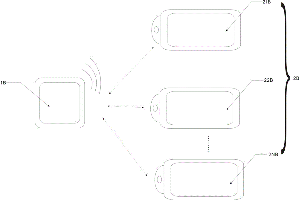
[0050] see Figure 4 , which is a wireless connection between one control terminal 1B and multiple receiving terminals 2B. Its specific working principle is basically the same as that of the first embodiment. It is the same from the standby stage of the self-generating module of the control terminal to the identification signal stage. The difference is , there are a plurality of different identification signals in this embodiment, different identification modules are identified and classified on the first identification module 15B, and sent to different receiving ends by the transmitting module 14B, for example, in this embodiment The first receiving end 21B, the second receiving end 22B and 2NB, the receiving module of the first receiving end 21B passes the identification module to the receiving end processing module, and the receiving end processing module on the first receiving end 21B sends the identification signal Give the second identification module, and identify, comp...
no. 3 example
[0052] see Figure 5 , is a structural schematic diagram of multiple control terminals 1C simultaneously controlling one receiving terminal 2C. In this implementation, it is composed of multiple control terminals such as the first control terminal 11C, the second control terminal 12C to the Nth control terminal 1NC, and each of the control terminals The process is the same as the process of the control terminal in the first embodiment and the second embodiment, and will not be repeated here. The difference is that after the identity matching is completed in sequence, the receiving module of the receiving terminal 2C according to the information sent by each control terminal 1C The signals are arranged and stored, and controlled sequentially. When the control signals are sent out at the same time, pairing or control is performed simultaneously.
[0053] Both the control end and the receiving end of the present invention are connected to a local area network at the same time, an...
PUM
 Abstract
Description
Claims
Application Information
 - R&D Engineer
- R&D Manager
- IP Professional
- Industry Leading Data Capabilities
- Powerful AI technology
- Patent DNA Extraction
Browse by: Latest US Patents, China's latest patents, Technical Efficacy Thesaurus, Application Domain, Technology Topic, Popular Technical Reports.
© 2024 PatSnap. All rights reserved.Legal|Privacy policy|Modern Slavery Act Transparency Statement|Sitemap|About US| Contact US: help@patsnap.com